


Tool/software:
Hi Ulrich, I hope this message find you well.
I need your help regarding to the design of 2kW PFC based on UCC28070. The problem regards the Vout regulation during transient load.
The voltage input specifications are 170VAC – 305VAC, for this reason I have designed the PFC output voltage at 450VDC, and due to maximum allowed size, I cannot use more than 880uF 500V elcap.
During the transient load from 0 to 5ADC (2,2kW) the output voltage swing from 405VDC to 495VDC and the DC-DC converter which is downstream ha regulation problems, therefore I must reduce as possible this deltaV.
To design the UCC28070 polarization I have used the UCC28070 Design Tool V.2, that you can see in attachment. On this spreadsheet I found two problems
- The sense resistors RR formula is circular, when you change the yellow cell change also the calculated value
- The RTX calculated seem wrong because in a range of 50 ohm and cannot be possible
UCC28070_Design_Tool_2.0_Output.xlsx
BTW I have designed the current loop and voltage loop to have PM > 45° at GM 0dB, as you can see on the spreadsheet, and the result is not as expected.
I have also added also 800uF to the current 880uF, as also I used the UCC28070A version, without any visible benefit in terms of output voltage drop.
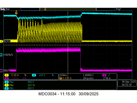
Below you can see:
- Vin 200VAC, Cout 880uF, Load 0 -> 5ADC, dV 92Vpk

- Vin 200VAC, Cout 1690uF, Load 0 -> 5ADC, dV 88Vpk
All values are visible on the spreadsheet; can you give me some tips to improve this performance?
If you need more info do not hesitate to ask me, I’m available also for a call.
BR/Roberto
