Other Parts Discussed in Thread: TPS22919, TPS22917, TPS22992
Tool/software:
Hello there,
Problems during startup when attaching a secondary battery to the BQ25505 have been reported several times on the forum. Basically the chip does not continue to provide power to the system if there is a short power outage during startup which can happen due to connection bounce when inserting a battery into a battery holder, placing a jumper connector or flipping a power switch. The image below illustrates the problem.
I want to propose and discuss possible solutions to this problem.
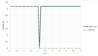
Image taken from Daniel E. in his post.
Related topics in the forum
- https://e2e.ti.com/support/power-management-group/power-management/f/power-management-forum/924082/bq25505-can-the-charging-efficiency-diagram-in-the-bq25505-data-sheet-be-simulated-by-software/3419128?tisearch=e2e-sitesearch&keymatch=BQ25505%252525207.4.3#
- https://e2e.ti.com/support/power-management-group/power-management/f/power-management-forum/858411/bq25505-output-voltage-while-on-secondary-battery-is-lower-than-expected/3178888?tisearch=e2e-sitesearch&keymatch=BQ25505%25252525207.4.3#
- https://e2e.ti.com/support/power-management-group/power-management/f/power-management-forum/1544756/bq25505-bq25505-not-allowing-battery-current/5944889?tisearch=e2e-sitesearch&keymatch=BQ25505%207.4.3#
Datasheet
The Datasheet describes the problem precisely but does not provide a solution. Datasheet section 7.4.3 "When no input source is attached, the VSTOR node should be discharged to ground before attaching a storage element. Hot-plugging a storage element that is charged (for example, the battery protector PFET is closed) and with the VSTOR node more than 100 mV above ground results in the PFET between VSTOR and VBAT_SEC remaining off until an input source is attached."
Solutions
- Waiting or manually discharging the capacitors on VSTOR. Not really a solutions for a non-prototype PCB.
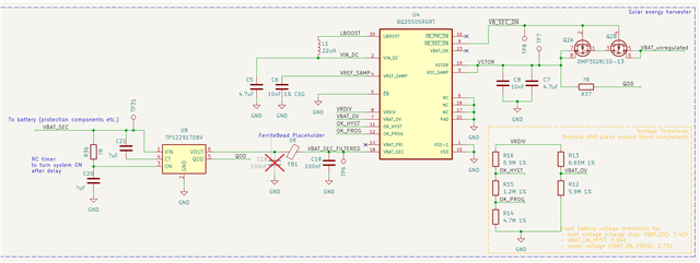
- Delay power connection from battery using a delay like 500 ms + a load switch (delay could be realized using RC circuit, or startup sequencer)
- Bonus: utilize external QOD functionality of load switch and connect it to VSTOR (not VBAT_SEC as usual).
- other ideas?
For the QOD load switch I could identify two parts from TI: TPS22992, TPS22917, TPS22919. From a first look theTPS22917 looks most suitable because of its low Iq of 0.5uA, low Ron of 80-120 mOhm. TPS22992 looks good as well but has high Iq with 10 uA (note that this will be always active which is not desired for a low power device).
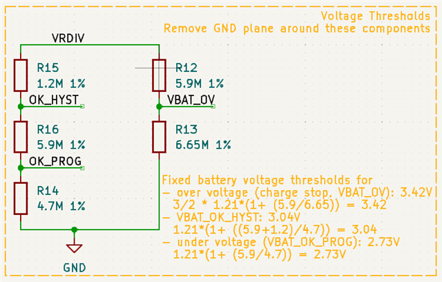
Please check the draft schematic below.
Checklist
We need to ensure a few things about the solution to keep BQ25505 functioning.
- Allow bi-directional current flow (discharge and charge the secondary battery)
- Low Quiescent current Iq (uA)
- Low Ron (mOhm)
- Slew rate compatible with BQ25505
Would this work or is there anything I am overlooking? Looking forward to other ideas.