This thread has been locked.

If you have a related question, please click the "Ask a related question" button in the top right corner. The newly created question will be automatically linked to this question.

TPS4HC120-Q1: Inductive load protection

Part Number: TPS4HC120-Q1


Tool/software:

Dear Sir/Madam,

I have been reading the TPS4HC120 datasheet and are a little confused on what protection is required to avoid
damage to the TPS4HC120/microcontroller if the supply or inductive load can get disconnected.
The supply cannot be reversed. The inductive load is turned on or off (no PWM). VS is 12V.
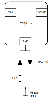
Below is a basic diagram where the following can occur.

(1) Power supply + or - are disconnected.
(2) Load + or - are disconnected.

Based on what I have read in the datasheet the TPS4HC120 can handle inductive load without additional TVS+Diode. 
Diode and resistor GND isolation is only required for reverse current.

Regards Joe

  • Hey Joe, 

    It looks like you are looking for designing for loss of ground and loss of battery protection. There is an application note that outlines the protections implemented to protect the device in these conditions. 

    https://www.ti.com/lit/an/slvaes9a/slvaes9a.pdf

    Loss of GND

    To protect against this double fault condition, appropriate design considerations have to be made to the resistor / diode network connected between the ground pin of the high-side switch and the local device ground. To protect against the described parasitic fault condition, it is recommended to increase the value of the resistor on the ground network to around 2 kΩ and to change the unidirectional diode to steering diode configuration such as the BAV199.

    Inductive Loading and Loss of Battery

    • Connecting a flyback diode in parallel with the load - In loss of battery potential on VS will be undefined.

    • Use of a resistor/diode network on GND pin and serial protection resistors

    The application note will have more information for this specific fault case. As for the + Load disconnect requirement this will be handled by the microcontroller based on the SNS pin output. 

    BR, 

    Alan

  • Dear Alan,

    Thank you for the response.
    I did read that note however my case is slightly different.
    As per my diagram.
    Input power and GND are supplied to the module via a connector.
    Load power and GND are supplied through the module.
    Module and load GND are the same.

    There are four cases for inductive load.

    (1) Load is powered and input power wire is removed.
    (2) Load is powered and input GND wire is removed.
    (3) Load is powered and output power wire is removed.
    (4) Load is powered and output GND wire is removed.

    As the module and load GND is common wouldn't just a flyback diode be needed to provide protection
    for the TPS4HC120 and microcontroller. ie. diode/resistor to GND and current limiting resistors to microcontroller are not required.

    Regards Joe

  • Hey Joe, 

    This is correct. As the module and load GND is the same only a flyback diode will be needed to provide protection.

    BR, 

    Alan

  • Dear Alan,

    Thank you.

    Regards Joe