LM5012: LM5012DDAR

Part Number: LM5012


Tool/software:

Hello

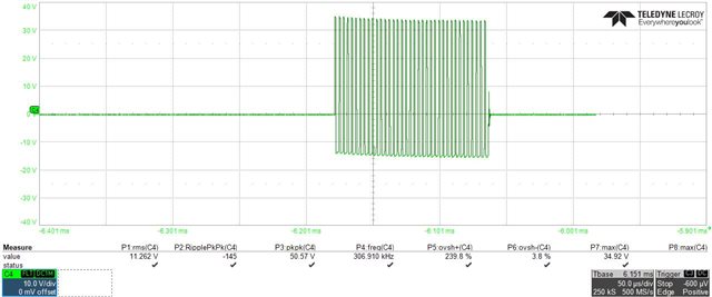
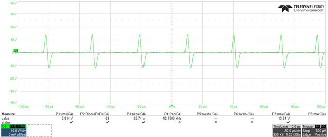
In power supply section we utilized a LM5012DDAR TI buck IC to convert 48V input to 12V output, for a switching frequency of 300KHz, we are observing ripple of 175mV across output capacitor (C67)  

Test case 1:

After increasing the output capacitance of the capacitor (C71, C72) to each 44uF -  ripple reduced to 94mV.

I’ve attached a schematic and output voltage waveform for your reference.

we have used - R174-3. Ohm, C107 - 220pF.

Kindly support us to obtain a minimal ripple voltage, Please get back if any further information required.

  • Hi Spoorthi,

    As you are using Type-3 ripple injection, you don't need electrolytic capacitors at output. Due to high ESR [wrt ceramic capacitor] the observed ripple at output will be higher. I would recommend you using high quality ceramic capacitors of equivalent capacitances [having sufficient voltage rating considering DC bias effect] across output to get minimum output ripple voltage.

    Regards

    Arpita

  • Hi Arpita,

    As per suggestion we did some test cases, summary is attached, 12V output voltage ripple is reduced along with switching frequency (Across the inductor)

      Ceramic capacitor  Electrolytic capacitor 

    Frequency(KHz)

    12V output ripple (mV)
    C71=20uF  C72=20uF  C71=22uF C72=22uF
    1     42.7 25
    2       31.2 23
    3     306.9 178
    4       331.12 297
    5     58.5

    34

    Kindly help us to resolve the issue 

    Regards 

    Spoorthi

  • Hi Spoorthi,

    Kindly Note that switching frequency should not change with 20uF or 40uF of output capacitor. I would recommend to double check the measurement method. Can you please attach the SW node waveforms for the above cases?

    Did you consider ceramic capacitor derating effect? What was the voltage rating of the ceramic capacitors?

  • Hi Arpita, 

    I've considered 20uF, 50V ceramic capacitor. Switching frequency is changing with the different capacitor not with the capacitance value.  I've measured switching frequency across the inductor and waveform has been attached for your reference 

    Inductor voltage with output electrolytic capacitors (C71, C72)

    Inductor voltage with output ceramic capacitors (C71, C72) 

  • Hi Spoorthi,

    Are you measuring voltage across inductor? Voltage between SW node with respect to Vout?

    To measure frequency, you need to probe SW node wrt GND [NOT across inductor}.Kindly share the same.

    regards

    Arpita

  • Hi Spoorthi,

    What is the load current at which you captured the above waveforms? Kindly note that in PFM mode during light load, the switching frequency reduces depending upon operating conditions and circuit parameters. Can you please measure at higher load current (CCM)?

    Regards

    Arpita

  • Hi Spoorthi,

    do you have any update?