


Other Parts Discussed in Thread: TPS56C230, , LM5171, INA226
Hey TI-experts,
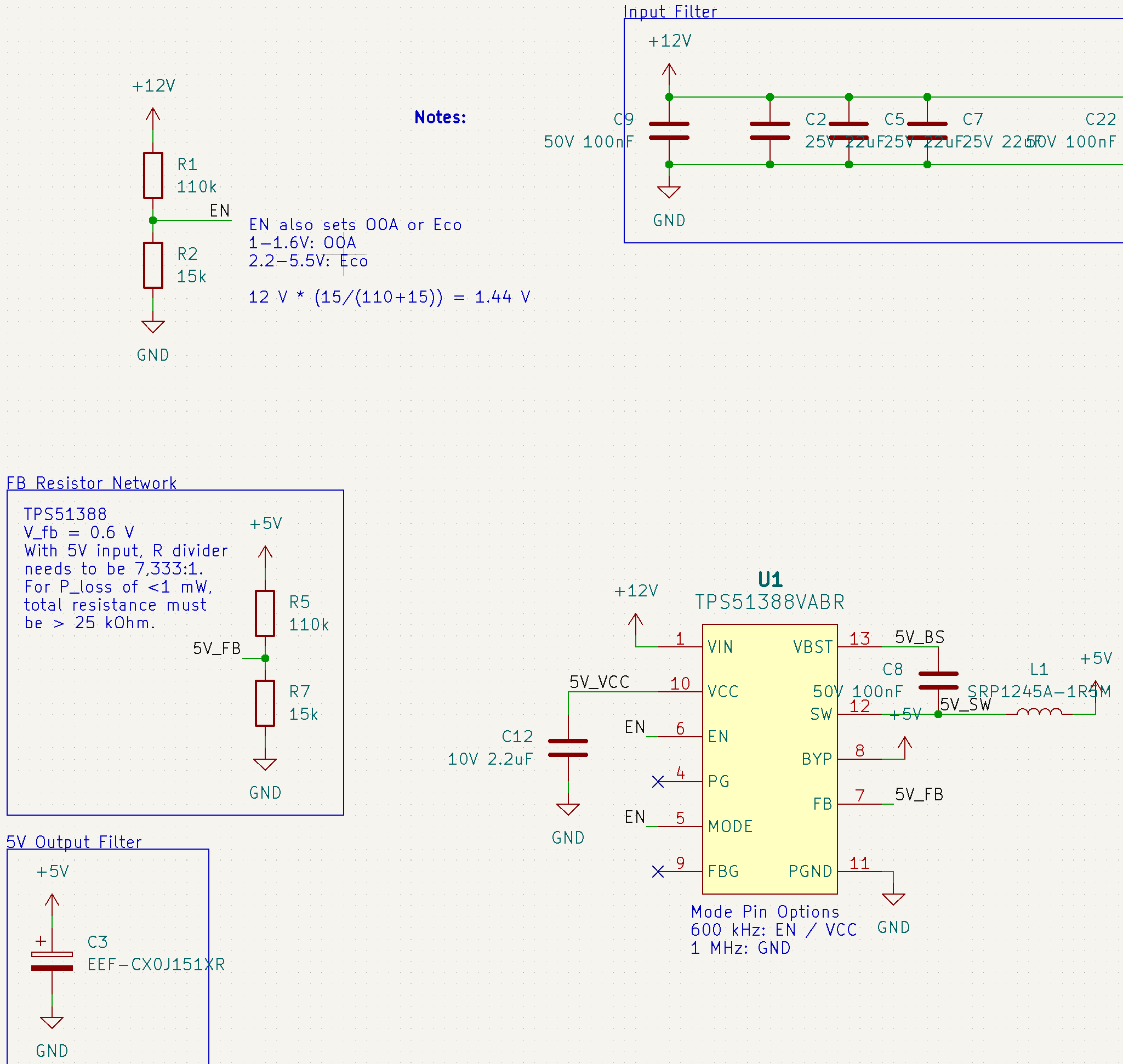
we now built two engineering samples featuring a new design with TPS51388 at the center of our power conversion. This new design was supposed to be a performance & efficiency upgrade over our existing TPS56C230 design, additionally using a much bigger SRP1245 inductor.
The goal is to convert 12V to 5V and 3.3V respectively using two TPS51388 converters, for up to 12 A output on both channels. We have an automatic efficiency sweep test that increases the load exponentially after an initial burn-in phase. The load settles for a few seconds before every measurement.
Our testing has shown the efficiency to drop sharply after 1.6A, staying ridiculously low up to around 10A, until it seems to follow the curve we were expecting. For comparison, I have added the curves for TPS56C230 (fsw: 500 kHz) with a much smaller 7028 inductor to show what the curves usually look like. Here, a much smaller design outperforms the new boards for no apparent reason.
Furthermore, we have tried to capture the switch node waveforms at different load points for evaluation (excuse the spikes, I couldn't get the probe ground lead shorter).
(We observe some hiccup behaviour at lighter loads (2A), where the SW node stays high much longer, dips down shortly for a few pulses, before continuing to switch at the expected duty cycle. This behaviour doesn't appear at higher currents though, so probably a false flag.)
Instead, at currents between 2-8 A, fsw dithers uncontrollably between 480 kHz and 800+ kHz, and I have no idea as to why! Only at higher currents does fsw lock in nearly perfectly at 600 kHz as intended.
Surprisingly, after resetting and when manually setting a high load (6-9A), again we observe clear waveforms and clean 600 kHz switching behaviour and conversion efficiencies from 12V->5V at 97%. When reducing the load at 0.1 A intervals, it starts the erratic behaviour at 5.2 A, with efficiencies dropping to 88% instantly. It doesn't seem to recover stable operation until the load is turned off, a higher load is applied, and 600 kHz switching continues in this regime.
We have never observed such behaviour with any other TI Buck converter before.
Screenshots of schematic and layout are attached. As you can see, the TPS51388 is configured to operate in OOA mode, we will check if switching to Eco should change anything. All parts were purchased at Mouser and the part numbers clearly show 51388 on the package.
Any help is highly appreciated, we'd all rather spend time with the family...
Merry Christmas!
PS: our load is regenerative using LM5171, efficiency is calculated using INA226. The testing board is designed in-house, and has served us well so far. We have not observed such an issue before and can testify that the DUT output exhibits the same ripple as on a resistive load; the testing input is filtered well enough not to cause issues.
1 & 2 showing the hiccup at lower loads (probably normal behaviour)

3 and 4 showing the erratic fsw behaviour

 5 showing a clean waveform when starting with a higher load

6 & 7 Schematic and Layout
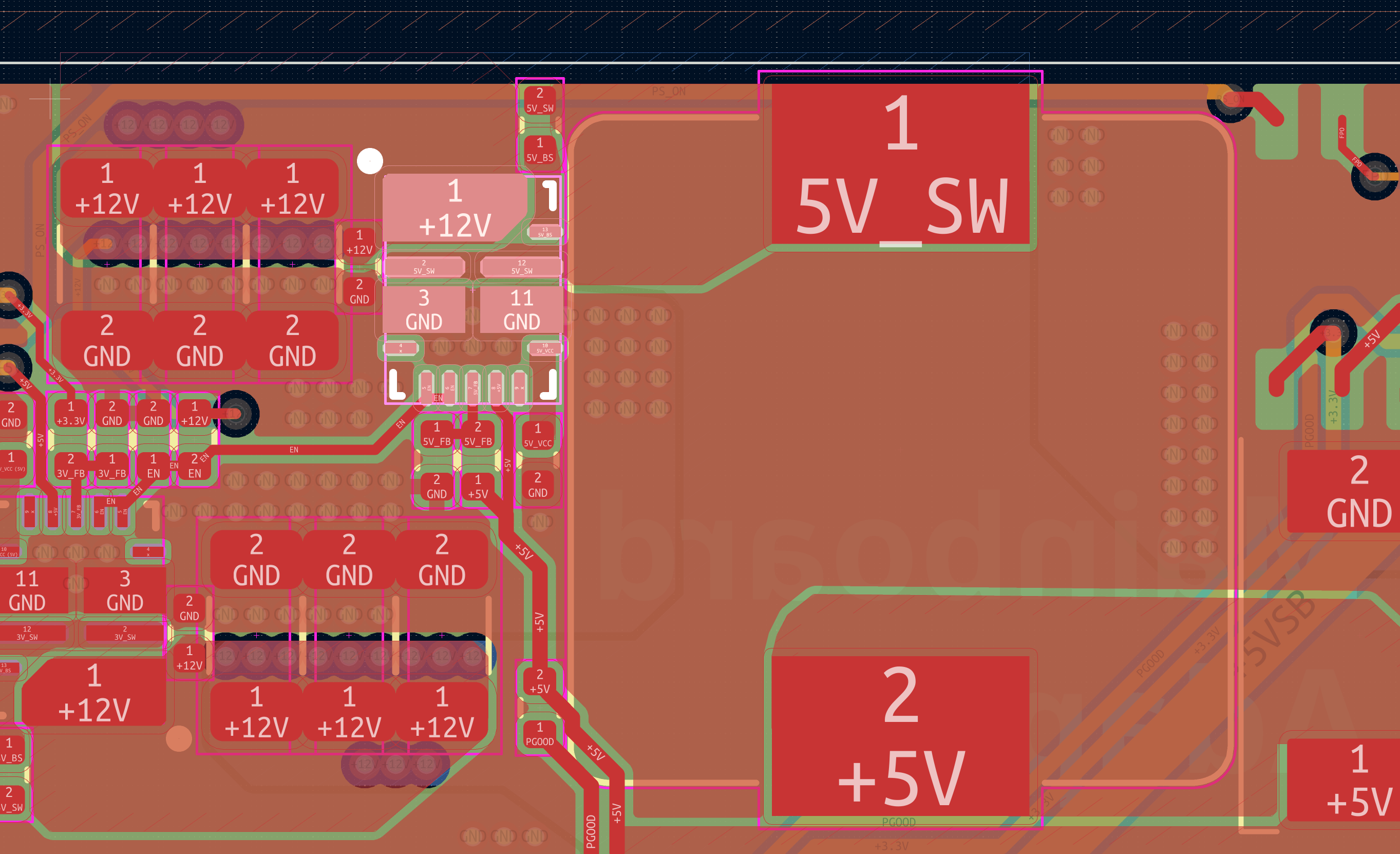
It is a 4-layer board with layer 2 of course being an uninterrupted Ground plane. We are insanely size constrained, otherwise I would have rotated the inductor 90° such that the SW node was even shorter, for even better performance, but I reaally don't think that is the issue.


