Hey,
I am using the bq27500/1 EVM to, well, evaluate the fuel gauge. My set-up includes a DC power supply and electronic load, both controllable through GPIB, as well as a second DC power supply, DAQ, sense resistor, and a 1500mAh cell phone battery. I have had a great number of questions and issues that I have sorted through already, though these remain:
(bqEASY wizard questions)
- During the bqEASY set-up wizard on page 2A, "Cell Characteristics", there are two columns of data in which to enter values. The first is for "PACK A" and the second for "PACK B". I have yet to find any documentation explaining appropriate values to enter in the event that one has only a single type of battery they wish to 'learn'. For instance, I have a 1500mAh Li-ion cell phone battery, so for pack A I entered 1 (cells in parallel), 1500 (nominal capacity), and 3000 (min rated voltage). I don't care about pack B so I entered all zeros -I have no idea if this is alright.
- On page 2H, "Miscellaneous Information", there are resistor ID values to be entered. I have yet to find any documentation explicitly stating what this actually means. I don't know the "value of Resistor ID A" (or B if there was one). I have the defaults 200 ohms and 7500 ohms. I believe when I performed the last learning cycle I simply entered zeros here as well. What is a Resistor ID? Is it appropriate for me to simply enter zeros?
- On page 4A, "Use Default Chemistry?", I'm unsure whether its appropriate to simply used the default chemistry and moved on. The battery I'm using is Samsung, though manufactured by SDI (noticed in the chemistry list), however I did not see the numbers in the list correspond to any of the numbers I see on the back of my battery ("EB575152YZ", "DPQ DC101209", "S/N: AA1ZC09xS/D-B"). I have been told by colleagues that most cell battery's are LiCoO2, so in the previous learning cycle I chose the default.
- On page 5A, "Learning Cycle", when I click the "All Done" button after completing the cycle I get the error regarding "Update Status1" not being 02. I had already gone through a few learning cycle failures before, so in my most recent attempts I have made sure to watch the process like a hawk and ensure the bits are being 'cleared' and 'set' when appropriate and that certain values related to pack A (ie. "Update Status0") are correct. My most recent learning cycle, as I just mentioned, still failed because of "Update Status 1". To get around this I've chosen to manually enter 02 into the field -everything is A-OK after this. I wanted to check that my action here is appropriate. If not, how else do I achieve a successful learning cycle?
(fuel gauging process questions)
I should quickly describe my set-up before asking this question. I have my GPIB controllable power supply and load daisy-chained together, so they both clip to "Load+" and "Load-" (this hasn't been an issue). I have my second power supply providing 2.5V to "2.5VIN" and "VSS" (the jumper is on external). Junction 8 (J8) has a thermistor from "T" to "Pack-". At junction 9 (J9) I have a wire from "Pack-" to the negative battery terminal and "Pack+", to a 0.1ohm sense resistor, and then to the positive battery terminal. There is a DAQ measuring the voltage across the battery terminals and across the sense resistor (used for current measurement). I wrote some software to control the load and power supply according to the current and voltage reported from the DAQ. All my data is recorded as well. - When I discharge a battery from fully charged to 3.0V at a C/3 rate (500mA) I noticed that the battery voltage reported by the evaluation software (EVSW) is noticeably offset from the actual battery voltage. For instance, when my program terminated the discharge at 3.000V the EVSW reported 2.845V. This is obviously not a trivial problem given the importance of the 3V termination point. At low currents this offset is negligible, as one would expect, but certainly not at expected currents (>300mA). Given I expect this voltage offset is due to a tiny resistance of less than 0.3ohms (lines and sense resistor) I can't help but wonder if there is some essential criteria I overlooked such as, "the battery must be as close as humanly possible to the pack terminals". Is this the case? Otherwise, is there some field in which I can directly enter the value of the resistance between the pack terminals and the battery? If there is, I have never heard it mentioned.
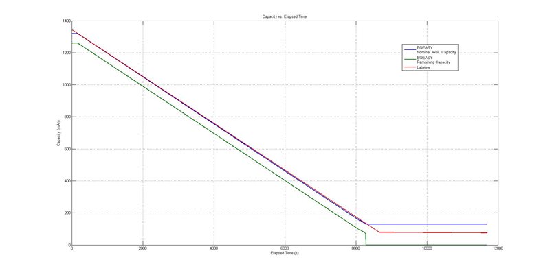
- What is the explicit difference between Nominal Available Capacity and Remaining Capacity? I know that one is "compensated" and the other is "uncompensated at C/20", but I don't know what I'm supposed to take-away from that definition. What is the compensation process? During the discharge process I mentioned earlier the two values are quite different and I just would like to have clarification as to why this occurs.
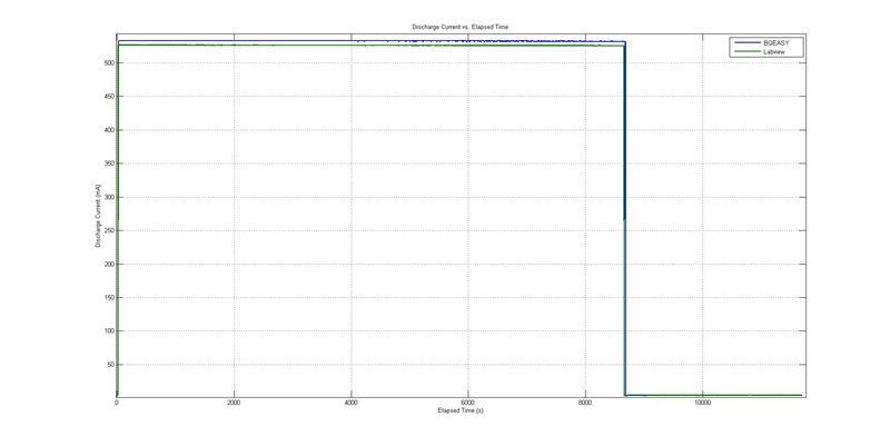
Thank-you tremendously for any help you can provide! To help you answer questions 5 and 6 I've attached 3 graphs to illustrate the data collected during the discharge process I spoke of.
Daniel