This thread has been locked.

If you have a related question, please click the "Ask a related question" button in the top right corner. The newly created question will be automatically linked to this question.

TLC5941 XERR

Other Parts Discussed in Thread: TLC5941

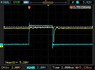
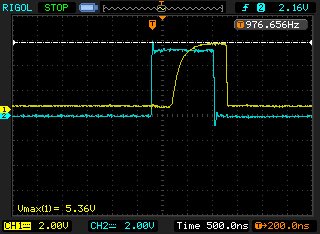
I'm looking at the TLC5941 and seeing a pulse on XERR just after the BLANK.  In the capture below, yellow is XERR (1k pullup), blue is BLANK.  This pulse seems to appear when I raise the current through 16 LEDs 100% duty cycle above about 50mA.  Could this be a temperature issue or is it a LOD (likely caused by not enough capacitive decoupling on the LED input)?  I am measuring a temperature of 75C on the outside of the package at 60mA.  If LOD, what is your suggested decoupling cap types and values?  I need XERR to be clean at high currents so I can carefully monitor temperature.

Thanks,

Andrew

  • Hello Andrew,

    When measuring XERR are you using the IC GND pin as reference? I just want to make sure that this is not a measurement problem. I can see some ringing on XERR even when just BLANK goes high and wonder if the GND connection of the probe is maybe somewhere far away from the IC GND pins.

    Normally you should not have gliches on XERR. It should either go low or stay high, even with high currents, but GND connection is very important when high currents are flowing through the IC.

    Best regards,
    Brigitte

  • Hi Brigitte,

    Yes I am pretty close to the IC GND pin for the reference.  In greater detail, the problem is not just this one glitch.  Given 3 dimensions: voltage, current, and # of LEDs, I see a clean and high XERR on low values of any of these.  Then when I increase any one of these, I start seeing XERR fall.  In fact, with a reasonable BLANK width, sometimes the only time XERR is clean is during BLANK :-).   If I continue to increase one of these dimensions, I see XERR switch from being mostly high to mostly low and then finally its cleanly low (except during BLANK).   I added a 100uF electrolytic, 4.7uF ceramic and .01uF ceramic cap across the LED supply to ground (IC supply to gnd has .1uF caps right near the chip).  Adding any of these caps moves the moment when XERR starts "acting up" to higher values.

    For example, at 4.4 volts, 500mA (20mA per LED with 25 LEDs (2 chips)) XERR is high (except for the drop shown in the prior email) with a 100 uF cap physically anywhere.  If I move it physically near the anode of the LEDs it stays high solid.  These are green/red LEDs that drop 2.2/1.65 volts.  But that initial drop occurs again at about 4.1v.  I can further reduce the LED voltage down to 3.4 volts and still XERR is high except for a gradually widening initial drop.  At 3.3 volts it suddenly flips, going entirely low.  Except for blank.  Below that the current starts to fall so at that point the circuit is under voltage.  Clearly, this is important because a lower LED voltage yields greater efficiency and less heat generated by the chips. 

    So it seems that XERR is very sensitive to current inrush issues -- if the LEDs don't have their own decoupling caps XERR can trigger even though really there's no visual issue. 

    I also noticed I had a "marginal" LED, it was a lot dimmer then the rest, and was causing a lot more or a mess in the XERR until I replaced it.  I wonder if the effects described above can be caused by other marginal LEDs -- these are well-used LEDs running on a test board. :-)

    On a separate note, I'm seeing a dela of about 400ns after BLANK rises before XERR starts (see attached image)

    Is this expected?  What is the smallest pull up I can use to make the XERR sharper?

    Regards,

    Andrew

  • Hello Andrew,

    "Adding any of these caps moves the moment when XERR starts "acting up" to higher values." What do you mean with this?

    For example, at 4.4 volts, 500mA (20mA per LED with 25 LEDs (2 chips)) XERR is high (except for the drop shown in the prior email) with a 100 uF cap physically anywhere.  If I move it physically near the anode of the LEDs it stays high solid. 
    Are you using the same power supply for the LEDs as well as the IC?
    When you move the capacitor closer to the anode of the LEDs, I expect that the voltage drop on the VCC of the IC is smaller when the diodes start to draw current, so if you could measure the VCC of the IC with the cap while you observe the drop and when the drop is gone, I expect that the VCC is cleaner when the100uF cap is closer to the anode.
    If this is the case, a bigger decoupling capacitor close to VCC should be able to help as well.

    These are green/red LEDs that drop 2.2/1.65 volts.  But that initial drop occurs again at about 4.1v.  I can further reduce the LED voltage down to 3.4 volts and still XERR is high except for a gradually widening initial drop.  At 3.3 volts it suddenly flips, going entirely low.  Except for blank. 
    Below that the current starts to fall so at that point the circuit is under voltage.  Clearly, this is important because a lower LED voltage yields greater efficiency and less heat generated by the chips. 
    The above description really confuses me. Please check the voltage on VCC and all OUTx pins to make sure that none of these voltages falls out of regulation causing the XERR to react.

    Which package are you using? The above delay could be caused by a thermal issue. When BLANK goes high, it takes time until the IC cools down below the TEF threshold.

    Best regards,
    Brigitte