This thread has been locked.

If you have a related question, please click the "Ask a related question" button in the top right corner. The newly created question will be automatically linked to this question.

TPS64203 - non-isolated AC/DC buck converter with no transformer

Other Parts Discussed in Thread: TPS64203, LM5085, LM5088

Hello TI --

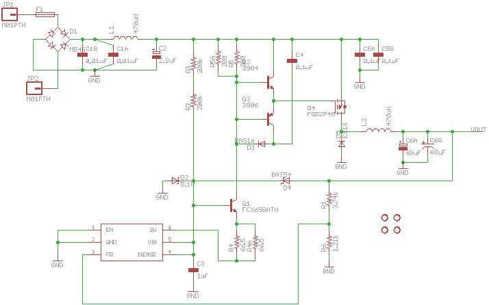
I'm interested in building an AC supply for a microcontroller/WiFi combo, with 120VAC input and 5VDC output.  To save on cost and space, I liked the idea of a transformer-less design, and came across this application note for the TI TPS64203.  I've since attempted to build this circuit, but now, I'm having some trouble getting it to run without throwing sparks. 

Thus far, I'm made the following observations:

1.  Immediately after assembly, I provided power to the circuit, and measured an output voltage of 1.68V across a load of 250 ohm.  I increased the load to 1kohm, and found that the output voltage was the same.  I measured the voltage out of the Rectifier bridge to be 160V (using a Multimeter), and the voltage across the D2 diode to be 4.6V.  I then noticed that I had the accidentally switched the R1 and R6 resistors.  Based on my calculations, the voltage on the FB pin (on the TPS64203) should be around 1.25V when the the output voltage is 5V and the proper resistors are used.   Instead, with an output of 1.68V, and the incorrect resistor placement, this caused the voltage at the FB pin to be slightly greater than 1.25V, and thus, the drive circuit was never turned on! 

2.  In my second attempt, I placed the R1 and R6 in their proper places, and turned on the circuit.  This is when the L1 inductor exploded.  I had assumed that an inductor rated at 100mA at the high voltage input would be sufficient, but I guess I was wrong.  Fortunately, I had a handful of the 1A rated inductors used for the output filter.  Realizing this was certainly overkill, I dead-bugged one of these big guys, and replaced the fried L1 part. 

3.  In my final attempt, with the new inductor, I switched on the power, and witnessed another spark.  This time, the spark came from the TPS64203 and the BAT54 (D4) diode.  There were black soot marks extending between the two ICs, and it appears that the diode had split through the top of the IC.  I'm not sure which IC is to blame here, so I'm hesitant to try again.

Now that I've got you up to speed on what I've observed, I'd like to talk a bit about my part selection for building this power supply.  As you may have already suspected, I'm no expert with building power supplies and working with semi-conductor devices, and thus, in my first iteration, I wanted to select parts that would be overkill for this application.  Furthermore, it can be seen in the schematic and board layout that I've included space for multiple packages for certain parts (C1, C5, C6, R4, R5) that I was unsure of.  In the testing described above, I initially built the board with the heftier parts (if I had a choice), and my intention was to test with the smaller, cheaper parts once the supply was working.  I've also included a link to a Google document, containing my Bill of Materials.  Note that the items highlighted in Red are the "less hefty" parts that were not utilized in the testing mentioned previously.  Follow the links to the DigiKey page for each item -- this is very helpful for locating datasheets for each part.

At this juncture, I'm not really sure how to proceed.  One concern that I have is that the traces around pins 1-3 on the TPS64203 are really close together.  I'm concerned that this may have allowed a short, but I can't be sure.  I probed all of these pin with a multimeter, and there seemed to be no shorts.  Does anyone have any suggestions?  Are there any more measurements that I can take to provide some additional insight?  I have a board mounted oscilloscope, so I can take detailed measurements; however, the inputs are limited to 20V.  Therefore, I'm limited to monitoring certain portions of the circuit. 

On another note, I'm finding that the FQD2P40 MOSFET has been discontinued, and it will be more and more difficult to obtain.  Fairchild suggests a replacement part for this, but I'm not sure if it will be a perfect drop in replacement.  Does anyone have an input regarding this?  Secondly, if things don't work out with this application note, does anyone have any similar circuits that they've built that they wouldn't mind sharing?  Something with a BOM would be preferable.

Thanks very much for any help!

Application Note:  "A low cost, non-isolated AC/DC buck converter with no transformer"

http://www.ti.com/lit/an/slyt391/slyt391.pdf

Bill of Materials - BOM:

https://docs.google.com/spreadsheet/ccc?key=0Am2etFM3DynNdExNNDNkMkFMcDJpUllmdjM4SlpraHc

Eagle Files:

7848.SmugPowerSupply.zip

Eagle Files (images) :

  • Attached is the BOM, schematic and board layout from which we wrote the app note.  Your BOM and schematic look okay.  It is difficult to review the layout without the part reference designators.  If you follow the board layout enclosed, it should work.  Note the placement of the high voltage components and how the buck power stage (Q4,D5,L2, C6 and C5) are placed.  Also, the size of C4 is critical.  The paper gives an equation that should help size the capacitance for C4.

    I did not know that FQD2P40 had been discontinued.  You will want to find a part will similar turn on/off characteristics in order for this circuit to work.

    sch_pcb_bom.zip
  • Thanks very much for your response.   I'll try to adapt your application circuit to pinpoint the source of error in mine.  I'll post once I've got things figured out.  Thanks again!

  • I am also designing non-isolated AC/DC buck converter with no transformer using the TPS64203, I would like to produce both +48V DC@ 5A and -48V DC@ 5A,  if I modify the some main switching circuit  for example FQDP2P40, D2 and Vin (pin5). Also I am considering using LM5085 instead of TPS64203, which is best solution? 

  • You will need to determine which solution works best for your system.  There are likely other devices that would work as well.

  • LM5085 quiescent current is too high to work in the same configuration as the TPS64203 AC/DC circuit.

  • Hi Jeff,

    Thank for your reply.

    My question is that I have a plan to design "A low-cost, non-isolated AC/DC buck converter with no transformer"  based upon your article. My specification is as follows:

    Input : AC 110V, 60Hz

    - Output:1: DC 80V, 500W

    - Output 2: DC 50V, 500W

    So I am modifying the main circuit part Q4, D5 and L2 but I have a diffculty in choosing the step down controller for 80V, 50V. In case of your design with for 5V and 750mA, my target is very high DC voltage and current. So, I am struggling with this issue myself to solve this problem. I also need to change the D2 and Q1 as well to meet the high voltage. Thus I posted my question, and I wonder if I could use LM5085 intead of TPS64203. Would you recommend the more related document for selecting step down controller for this design. I would appreciate if give me some advice for my design. What if I could use high quescent current you comment last time?

    My final specfication is that I will add LM116 to get +48V@5A, -48V@5A and more DC outputs after output 1 terminal. Also I will add the LM5088 to get +12V@5A, -12V@5A and more DC outputs.

  • The TPS64203 based design will not have enough gate drive to drive that kind of power out of any FET, esp the PFET that is required for this type of design.  I suggest you look at the link below for similar reference design that our design services team has already built and tested.

    http://www.ti.com/lsds/ti/analog/powermanagement/power_portal.page 

    then scroll down to PowerLab.

  • Hello Jeff,

    Does TI offer an evaluation kit for this design? Or something similar? I'm looking for a low cost AC-DC solution very similar to this design, and it would be extremely helpful to have an evaluation kit.

    Thanks,

    Joshua Franz

  • Thank Jeff,

    I would like to use your low cost non isolated AC/DC buck converter for our application which has 800W. The PWM controller supported current is around 3A, but  maximum current is too low, would you recommend another pwm controller with same function, but current has more than 30A. After this buck converter, I will add DC/DC converter.


    Regards

  • Hi Jeff, 

    We plan to work on a design that would be able to allow AC and DC power supply by the same port. This design seems to be interresting providing the controller and the gate drive circuit will allow 100% duty at low voltage input. Providing the fet Rds(on) and rectifier bridge Vf is lower enough to avoid dissipating a lot of power. Do you expect that a variant of this topology could be able to allow an output of 8V, 30W with an input range of 9 to 80VDC and 80 to 240VAC. 

    Many thanks for your lights, 

    Best regards,

  • I think it will be difficult to develop a gate drive stage that will work and/or find a PFET with low enough RDSon to make the circuit practical.  There are other ICs that are design for the type of application you want.  I suggest searching the power reference designs on the TI design website.

  • HI Jeff, 

    Many thanks for your quick answer, it is really appreciated. According to your comment, PFET that allow low power dissipation are quite expensive and not easy to find. We could expect that power dissipation could also become an issue in the passive rectifier.

    This circuit is intended to be a first stage of 2 in our design. It is followed by a wide input buck-boost regulator that deliver a 24V, 30W output from a possibility of multiple power source. To reduce the current in the circuit maybe we could forget to feed it with voltage lower than 65VDC. We could also be able to accomodate an output of 60V 600mA to reach our needed 30W at the output. The circuit could be bypassed for DC input lower than 65V. Do you expect that this circuit could be able to deliver 600mA at 60VDC at the output with an input range slightly expended down to 65VDC ? Will the MOS drive be compliant with this in/out range ?

    Best regards,