This thread has been locked.

If you have a related question, please click the "Ask a related question" button in the top right corner. The newly created question will be automatically linked to this question.

TPS61027DRC boost switching regulator to generate 1Amp output load current

Other Parts Discussed in Thread: TPS61032, TPS61253, TPS61027

Hi,

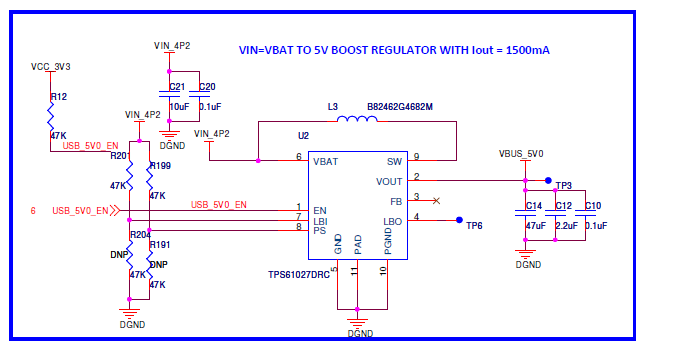
We are using TPS61027DRC boost switching regulator in our design to generate 1.2 Amps load current (USBport1=500mA + USBport2 = 500mA + 5Voltdevice=150mA).

Please help me to review the attached part of schematic and kindly le me know will this regulator is more than enough to generate 1.2Amps load current.(as switching current given in the datasheet 1.5A).

Regards

chandrashekhar.V

  • Per the datasheet figure 1, this is not a high enough current part.  The current rating for boost converters in the switch current limit.  The current in the switch will always be higher than the output current due to the step-up ratio.

    For a 3.3V to 5V at 1.2A converter, you need at least a 2.2A switch IC assuming an efficiency of 80%.  The TPS61032 or TPS61253 provide this.

    Also, be sure and read the datasheet for the device you choose and make sure to follow its guidelines for passive components and layout.  The ceramic capacitors shown on your schematic above are not recommended with the TPS6102x.

  • Hi,

    Please see this URL..

    http://focus.ti.com/paramsearch/docs/parametricsearch.tsp?family=analog&familyId=490&uiTemplateId=NODE_STRY_PGE_T

    According to this load can increase up to 1.2Amps. Please let me know what will be the maximum load we can connect on TPS61027DRC regulator.

  • As I explained in my previous post, the current rating for a boost converter is the switch current limit.  Since the Vin and Vout can be anything for a given part, and since the maximum output current depends on Vin and Vout, there is no way to specify the output current for a boost converter without knowing Vin and Vout.  So, in the parametric search that you found, we specify the switch current limit for the IC.  This is the important parameter and what you need to know.

    By reading the datasheet for a given part, you come across an equation like equation 4 in the TPS61027 datasheet, that explains how much output current you can get.