This thread has been locked.

If you have a related question, please click the "Ask a related question" button in the top right corner. The newly created question will be automatically linked to this question.

BQ24079T - Battery Detected with no Battery Connected

Other Parts Discussed in Thread: BQ24079T, SN74AUP1G80, SN74LVC1G80

Hi,

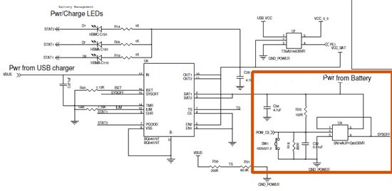
The problem is with the BQ24079T charging a LiIon (and powering a small circuit) from 5.0V USB input.

With no battery plugged in, but USB 5.0V applied to the BQ the CHG LED lights (i.e. CHG* goes low).

I have a small circuit that is always powered (to toggle a flip flop with a NO momentary switch).
Hence, there is always a wee bit of current draining the battery (and, apparently, if there is not a battery!)

This wee current is drained by a SN74AUP1G80 flip-flop which uses about 10 uA of current. As it turns out the flip-flop input cannot handle the max 4.1V from the LiIon so I had to put a voltage divider on the D input amounting to 302 kOhm, which could draw another 4.1v/302k = 14uA. It ~seems~ like my circuit (attached) would only draw a small amt of current, perhaps 24 uA.

Note: I wasn't happy with drawing this much current continuously and wanted to eliminate the divider, so I went to flip-flop SN74LVC1G80 that could withstand the 4.1V and eliminated the divider thereby drawing even ~less~ current, but still the little CHG LED stays on like some hollow little demon eye staring me down! ;-)

I see that the battery detection current for the BQ24079T, IBAT(DET) , is a minimum of 5mA and a maximum of 10mA (p. 5 of data sheet), so why would the CHG stay low drawing such little current?

The kicker is I can attach the battery and the CHG light goes out after it charges! But as soon as I pull the battery, the CHG LED comes back on!

I thought I might be reading the flip-flop data sheets wrong and they are drawing more current (most likely answer), but the CHG does go out when the battery is fully charged.

Any advice?

Thanks in advance,

Kevin

  • Hi Kevin,

     What is the voltage on BAT pin when there is no battery? When the battery voltage falls below VRCH, the battery detection routine should be happen. Please see figure 2 and 3 in the DS. Why pin 1 and 4 of the flip flop connected together? Please send some scope pots of BAT & CHG pins.  

     -Tahar

  • Hi Tahar,

    Thanks for the prompt reply. 

    The charged battery is plugged in I see 4.07V (it is a 4.1V LiIon) on BAT and the CHG LED is OFF.

    I just unplugged the battery and left the USB charging voltage source connected and the CHG LED did not (in this case) turn ON.
    BAT is small ~18.0mV

    If I remove and reapply the USB charging voltage source with the battery disconnected the CHG LED turns ON and BAT is 0.826V

    The flip-flop circuit has Q* (pin 4) tied to D (pin 1). Pin 2 is the clock (sorry about error in original posting). Every time SW1 is engaged the Q* changes state (due to feedback to pin 1).  This circuit works fine.

    Based on what I have found this morning, it seems that there are two states. 

    I am in India and do not have access to a proper scope. However, I can answer your questions by taking periodic readings if you like. Otherwise, I can connect my laptop as a scope if needed (but is not as good as the real thing).

    Thank you Tahar,

    Kevin

  • Hi Kevin,

     Based on your description on BAT pin, the battery detection routine is not running properly, the charger thinks that the battery still connected and at low charge level. Some how the small circuit of the flip flop on pin 5 is not providing the proper voltages during the battery detection routine as described on page 22 in the datasheet.

     If possible, plot pictures on the BAT pin (voltage and currents) will help us understand what is happening during the battery detection routine phase.

     -Tahar

  • Hi Tahar,

    So I am in the market for a good inexpensive oscilloscope. They are pretty easy to come by in the US but a much more difficult in India.

    However, I want to comment on your reply: Yes, it seems the flip-flop circuit is sometimes consuming enough current to trick the BQ into thinking a battery is present. I believe it is dependent on whether Q* is 0 or 1. Neither state will affect the BQ with the USB power connected though (i.e. you cannot turn it off with SYSOFF with USB power connected). So, I will recreate the problem and check the Q* output of the flip-flop to see if that is the problem. I was thinking maybe I can limit the current out of the flip-flop or somehow get the circuit to draw less power.

    Anyhow, in the current scenario, if the USB power is not connected (just the battery) then CHG behaves. However, it seems like the flip-flop circuit may just may keep charging the battery above and beyond what is needed if it is tricking the charge circuit. So, as an idea to throw at you, I think to disable the flip-flop circuit (i.e. cut off its power) when the USB power is connected. It seems like that would solve the problem and keep CHG proper.

    Please let me know what you think. I would need a recommendation for a SPST switch that could be N.C. and switched open by the USB power input.

    Thanks!

    Kevin

  • Hi Tahar,

    I just re-read my post and wanted to add something.  The charge light does go out when the battery is fully charged, but sometimes it take a very very long time for it to charge that last 0.03 V or so. BUT it does go out.  I think this problem is related to having that flip-flop circuit hanging there...I don't think it could be anything else!  I have to get a switch of some type in place that cuts power to the circuit when the USB power is connected...I don't think I have any choice.

    Thanks,

    Kevin

  • Based on your description, yes!

  • Hi Tahar,

    I just wanted to update you. The power switch circuit is the definite problem. If Q* is low then the CHG light is not lit with battery absent. So, I am working to minimize the current drawn by the circuit as I also believe that it accounts for the fact the CHG remaining active while the battery appears to be charged (again this is dependent on whether Q* is high or low). I posted in the logic section and got a good reply that said I could add a diode and eliminate the 200k voltage divider. I think this will do the trick w.r.t. keeping CHG accurate. However, I'm looking for a switch that would turn the circuit off entirely when VBUS is connected. Here is the posting:

    http://e2e.ti.com/support/logic/f/151/p/194525/695138.aspx#695138

    If you read it and have any ideas please feel free to comment. 

    Kind regards,

    Kevin