This thread has been locked.

If you have a related question, please click the "Ask a related question" button in the top right corner. The newly created question will be automatically linked to this question.

TPS2540A - Manual control of ILIM0/1

Other Parts Discussed in Thread: TPS61240, TPS2540A, TPS2540, TPS2543, TPS2552

Hi,

We need manual control of standard downstream port current levels (100mA and 500mA)
from our board which is a host (an Android USB accessory) which plugs into the USB of
an Android-based mobile (see http://developer.android.com/guide/topics/usb/index.html)

Our board is already successfully transmitting data and charging every Android mobile we
have tested. We have a very simple setup:

  • Our Stellaris-based board has a USB stack that currently runs in HOST only mode and provides VBUS to an Android device (which is running in accessory mode, as a USB client, hence it needs the power from our USB device)
  • The Stellaris detects the USB connection, enumerates, and configures. We always supply max current on VBUS from a TPS61240 (450mA max, but this chip was used in the TI EVM to supply charging current on their host port so we continue to use it). 
  • In other words, VBUS is just the output of the TPS61240 5V DC converter which can supply up to 450mA (with some analog conditioning) connected to the USB 
  • VBUS. There is no control of this current or voltage, it is directly connected to the USB connector.

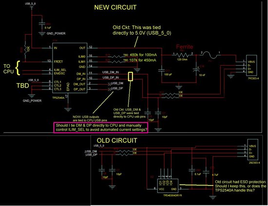
Please refer to the lower half of the schematic below for a look at our old circuit.

This always works wonderfully, but the problem is we want more control of how much current is
sourced from the limited battery of our board! Essentially, we want to at least be able to switch
to a low-power mode of 100mA to optimally preserve the battery of our board and the Android mobile.
(So that both devices exhaust their batteries at around the same time).

It seems simple, but I have run into problems adding this simple capability.I have chosen a TPS2540A and ~thought~ I could manually switch between low current and
high current modes (~100mA and ~500mA respectively) and avoid the automated switching, but there is nothing in the data sheet that details how to do this.

However, two things I noted in the data sheet:

  1. "The ILIM_SEL pin allows the system to digitally select between two current-limit thresholds, which is useful in end equipment that may require a lower setting when powered from batteries (versus wall adapters)" Note that our board is an example of this battery powered example case.
  2. "In the case of a USB 3.0 host, the super speed differential pairs must be routed directly to the USB connector without passing through the TPS2540/40A/41/41A"

Now we are not USB 3.0, but it would seem that I can route the DM/DP lines around the 2540 and manually switch the current with ILIM_SEL.

Can anyone confirm this statement? Further how do I set up CTL1-3? In the new circuit in the schematic below I have setup the CTL1-3 lines for SDP USB 2.0, but should this even matter if I manually control the current limit?

There is one minor wrinkle. Some Android tablets may run in host mode, so we want to
detect the host and shut off our VBUS in this case (this is not required functionality at this point).
However, if the Stellaris detects a host via the (directly routed) DM/DP lines it might use EN/DSC
to shut of VBUS connection to that host.

Finally, there are plenty of features of the TPS2540A that I want to use, but many that I don't.
Am I better off with some other chip or a custom design?

Thanks in advance.

Kind regards,

Kevin Kreger

  • It seems like you need more of a charging circuit that can linearly regulate current. TPS2540 is a protection switch that can be used in charging applications but it is the portable device that regulates the charging current and not the TPS2540. The current limit setpoints in TPS2540 pass any current below the limit but foldback and regulate at and above the current limit setpoint.

    As far as USB 3.0, the TPS2543 is a newer part and supports charging of more of the new portable devices. The EVM for TPS2543 has USB3.0 connectivity and does pass the super-speed signals thru the board while routing the low speed D+/D- thru the TPS2543 data line switches.

  • Hi Eric,

    Thanks for the prompt reply!

    It seems like you are recommending just using a charging circuit. Can you suggest a charging IC/App note? As well, I could not quite get this sentence you wrote: 
    "TPS2540 is a protection switch that can be used in charging applications but it is the portable device that regulates the charging current and not the TPS2540."

    By 'it' what were you referring to? It seems like you were going to recommend something more specific

    I'm not interested in USB 3.0, I was just pointing out that you could bypass DM/DP per the data sheet, as that might be what I would do for my situation, but the point is moot as I will be looking at charging circuits/ICs per your recommendation.

    I would really appreciate just a little more direction. I don't usually do USB stuff (yeah, you could probably tell :)

    Thanks Eric and have a great evening.

    Kind regards,

    Kevin Kreger

    F

  • Sorry about the vagueness, Kevin. I support the TPS2540 (and variations) but am not proficient with TI's charging solutions. Can I "move" this thread over to the Battery Management forum?

  • Eric,

    Please move it however you like to get maximum help for me.

    But I want to be clear I need a adjustable current-limiting device that provides 5.0V not a battery charger. I've been searching since my last post and everything that is close is a "Adjustable, Constant-Current, Current-Limited Power-Distribution Switch" and these devices are all in the sub-family "USB Power Switch" Please understand I am not charging a battery, but I am a battery powered device that is connected to a mobile via a USB cable. My device is a USB host, thus it has to provide 5V on the USB cable. Hence, I am only trying to control how much current is drained from my device by sending 100mA or 500mA at 5V. This is exactly what "USB Power Switches" are designed to do. For example the TPS2552 would be a great solution if I just wanted to provide 5V with a single current limit such as 100mA. Now I'm looking for something like the TPS2552 that has the abilit to switch between two ILIM currents, but does not have the features of the 2540 that I do not need. If I use two 2552s and switch them I end up eating more CPU lines and the solution may be more expensive. Hence, if there is something like the 2540, or a simple way to just use the 2540 to switch the two current levels manually.

    Thanks Eric!

    All the best,

    Kevin

  • I think TPS2552 would be perfect. Take a look at the application circuit on page 27 (Figure 27. Two-Level Current-Limit Circuit). Setting R1=272kohm and R2=64.9kohm will theoretically get you the 100mA/500mA switchable thresholds. One control signal is needed (same as TPS2540A ILIM_SEL).

    The recommendation is to keep the ILIM resistor below 230k (to yield specified current limit accuracy) so 272kohm for R1 may yield slightly worse accuracy at the 100mA setting.

  • Hi Eric,

    Just got an idea...maybe I can use the TPS2552 or something similar and switch in 2 different values of current limiting resistance Rlim. Thoughts?

    Thanks!

  • ERIC...THAT'S PERFECT!!!! :-) :-)

    I can go to bed happy now (it's 1a.m. in India, which is my current location)

    Have a great afternoon and weekend!

    ALL THE BEST,

    Kevin