This thread has been locked.

If you have a related question, please click the "Ask a related question" button in the top right corner. The newly created question will be automatically linked to this question.

Using Simple Switcher to generate a positive output voltage from a negative input voltage (stepdown)

Other Parts Discussed in Thread: LM741, LM2733

Hello:

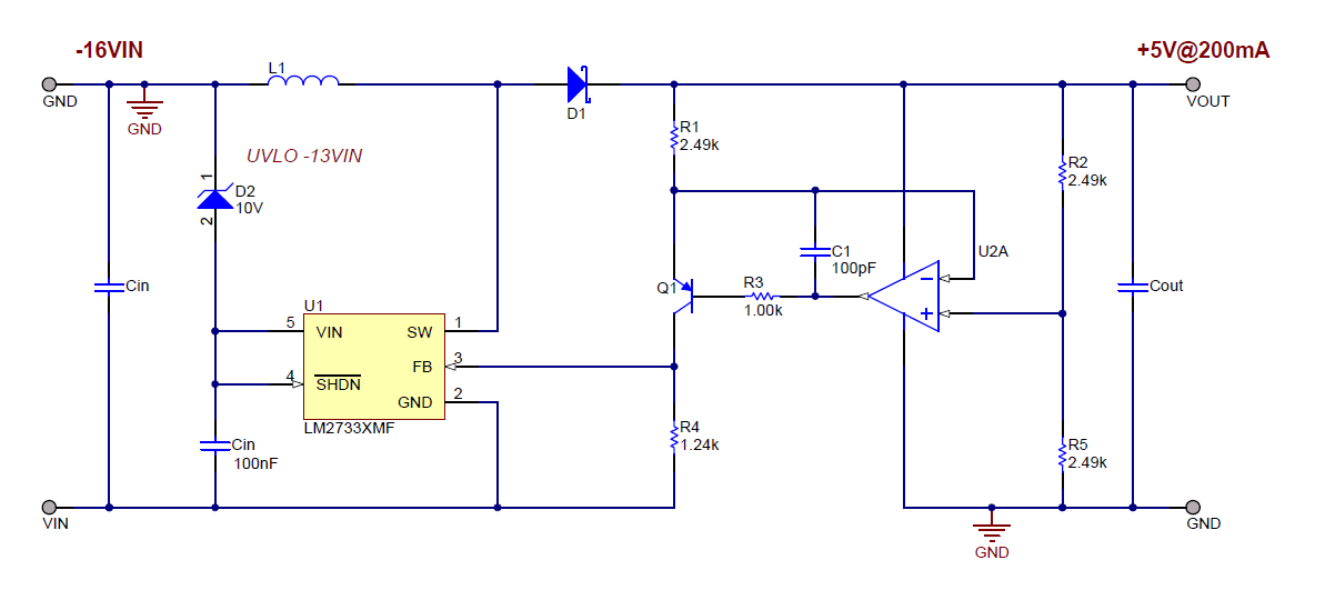
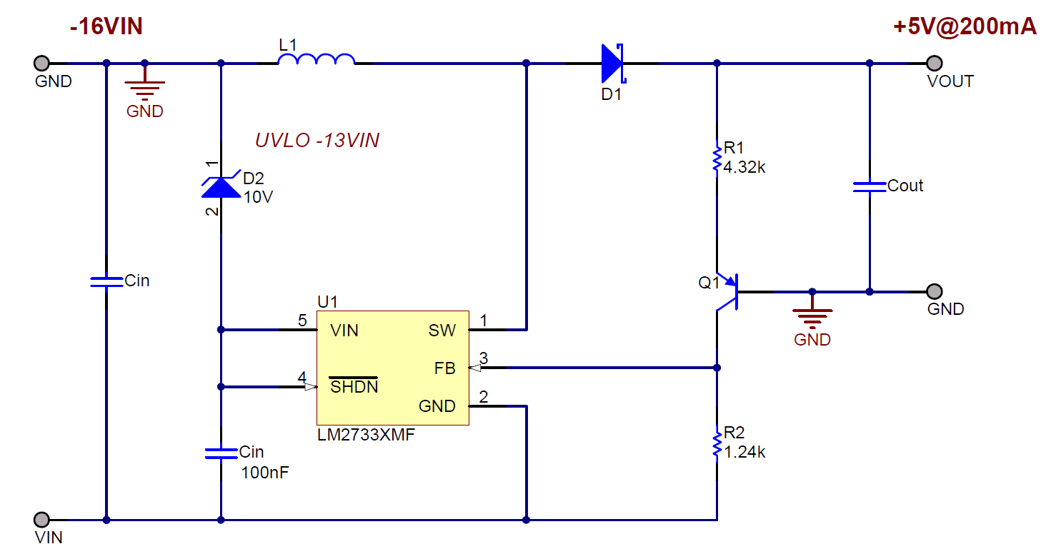
I would like to know how to use a simple switcher to invert a voltage, generating a positive output voltage from a negative input voltage.

I only need about 200ma of output current and my desired output voltage is +5v with a -16V input voltage.

Is this possible?

Thanks,


Alan

  • Hello Alan,


    please take a look at the following schematic and let me know if you need any further herlp.

  • Hi Giuseppe:

    Thanks for the reply.

    A few questions.

    Any way to do it with less parts.

    Also I would need some details (specs) on the parts required:

    1) Diodes

    2) Inductor

    3) Transistor

    4) OpAmp

    Thanks,

    Alan

  • Hello Alan,


    please take a look at the following schematic, it can work but it would not be as precise as the previous one because heavily depends on the temperature.

    For what concern diodes and inductor it depends on your application. You can use a schottcky diode and an inductor of 10uH.

    For Q1 transistor you can use MMBT3906 and for the op-amp you could use LM741.

    Use about 10uF of output cap and 10uF for the input cap.

  • Hi Giuseppe:

    Thanks for the reply.

    Can you tell me which resistors set the output voltage for both of the circuits provided and the calculation required if I want to change the output voltage to say 3.3v for each of these circuits.

    Thanks again,

    Alan

  • Hello Alan,


    on both circuit is applied the same principle, a mirrored current flows through the feedback resistor in order to generate the correct feedback voltage.

    For the circuit with the OP AMP:

    1. the resistor divider R2-R5 generates 2.5V at the non inverting input of the op amp.

    2. the op amp is in buffer configuration therefore the voltage across R1 is 5V-2.5V=2.5V

    3. current that flows through R1 is 2.5V/2.49V = 1mA and it is mirrored on the collector of the pnp BJT

    4. in order to generate the correct feedback voltage of the LM2733 (1.23V), the resistor R4 is equal to 1.23/1mA = 1.24k


    For the circuit without the OP AMP:

    1. let us assum that 1mA is flowing through R2 (mirrored current) hence R2 = 1.23V/1mA = 1.24k

    2. R1 is (5V-0.7V)/1mA = 4.32k

    3. the votlage drop across the emitter base junction of the BJT is heavily thermal dependent therefore the regulation won't be accurate


    Regards,

    Giuseppe