This thread has been locked.

If you have a related question, please click the "Ask a related question" button in the top right corner. The newly created question will be automatically linked to this question.

TPS62112 - voltage applied at the output

Other Parts Discussed in Thread: TPS62112, TPS62143, TPS62163, TPS62141

Hello,

I would like to use the TPS62112 in my new design. The user is offered 2 options to power the module:

 - Using 12V which is converted to 5V using the TPS62112

 - Using 5V directly on another input

How will the TPS6211 react when 5V is supplied directly to it's output pin (or the inductor), and the input is not used?

Thanks!

  • I don't know the answer to your question directly, but am I correct in assuming that you are asking because you want to give the user a way to power your widget directly, and that would expose the output pins to the 5v being supplied from another source?

    If so, I would,suggest incorporating a diode or simple method to limit current flow in the circuit so that it would block current going into the output pins of the TPS62112. That would ensure that there was no damage to the TPS IC and also,that the TPS IC wouldn't add any unexpected effects to your power supply or to,the circuit it is supplying.

  • Instead of the older TPS62112, how about the new TPS62143 (or TPS62163 if you only need 1A) family?

    All of these device and the TPS6211x are ok with having a voltage applied at the output.  Note that this voltage will appear at the input to the IC due to the high side MOSFET's body diode.  So, if you have other circuits running on the 12V bus, these will be powered from the output, through the input.

  • Hi Chris,

    Thanks for your feedback. For now I prefer to use the TPS62112... are there advantages to use the newer ones?

    I understand that putting 5V on the output will work fine, and in this situation the 5V will also appear on the input.

    One last question: what happens when there is 5V on the input (USB connected) AND there is also a battery connected (12V on the input)? I would think putting a resistor in series (with the 5V USB input) to limit the current flow would be sufficient?

    Thank you for your feedback! Much appreciated.

  • The newer parts support much smaller solution size, higher efficiency, better transient response, etc.

    If there is 12V on the input and 5V in the output, then the body diode will not conduct.  No current will flow, if the IC is disabled.

  • Now I see, the inductor is a lot smaller because of the higher switching frequency! That is indeed useful.

    None of the recommanded inductors for the TPS62141 is available from digikey....

    (1) s any shielded 2A inductor with 2.2uH inductance good enough? 
    (2) Can I use the inductors specified in the TPS62141 (1A) datasheet for the TPS62143 (2A), assuming my design won't use more than 1.5A?

    You mention "If there is 12V on the input and 5V in the output, then the body diode will not conduct.  No current will flow, if the IC is disabled". Why do you add "if the IC is disabled?".
    (3) How can I disable the IC in such situations?
    (4)What if the IC is not disabled? 


    Thanks!

  • Yes, any 2.2 or 3.3 uH inductor that meets the saturation current needs will work.

    You can disable the IC by pulling the EN pin to ground.  If the IC is left enabled, then it might switch to increase the 5V output to its setpoint.

  • Hello,

    The reason I could not find the inductors at Digikey is because there is a typo in the datasheet:

    IHPL1212BZ-11 should be IHLP1212BZ-11

    Please pass this on to the responsible to fix it.

    Just one question: the datasheet (http://www.vishay.com/docs/34289/lp12bz11.pdf) says the frequency range is 1MHz, but switching frequency is 2MHz? Isn't this a problem?

  • There is a submit documentation feedback link at the bottom of the datasheet pages.  Please use this to report such errors.

    The inductor worked fine in our testing.  Vishay should be contacted as to this note in their datasheets.  Better efficiency might be achieved with a coilcraft inductor.

  • Hi,

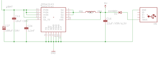
    Would the attached example be OK if I wanted to mix USB 5V (optionally plugged in) and the TPS62143? I am reffering to the diode in particular.

    Use cases the solution should be able to handle:

    • Only battery connected: OK!
    • Only USB connected: OK (ignoring voltage drop over diode)
    • USB and battery connected: ???

    Thank for your time,

    Tom

  • You can test it out on the EVM to make sure, but it should work fine.  For both sources plugged in, the diode will be off due to its high forward voltage.