This thread has been locked.

If you have a related question, please click the "Ask a related question" button in the top right corner. The newly created question will be automatically linked to this question.

LM22670 burning at startup / shutdown

Other Parts Discussed in Thread: LM22670

Hello,

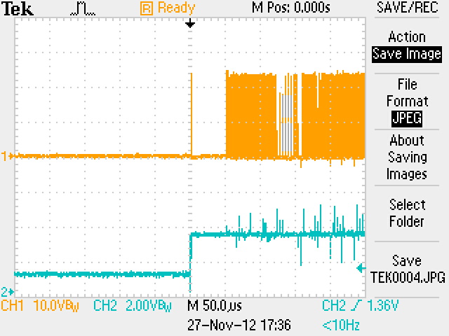
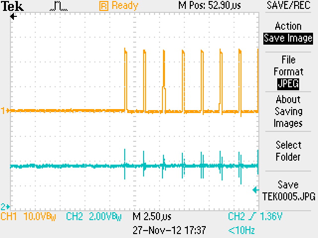
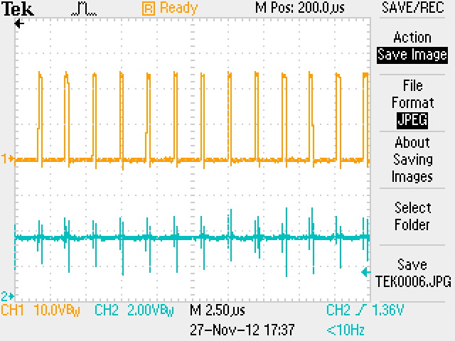
I'm experiencing a 15% to 25% of failures at startup (or shutdown) for LM22670-ADJ. After some minutes it starts to burn and if power is not removed it eventually melts.

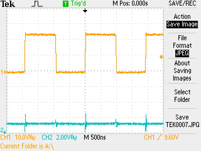
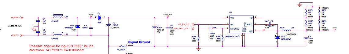
Vin=25V, Vout=12V, power consumption is lower then 1,0 A.

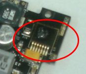
The schematic is the one below:

We did not experience this failure with the first small batch of production (30) but the failure came out at the second batch (>100).

The CPU is syncronizing the frequency at 500KHz and enables the device after about 10 seconds from power on (when CPU finishes other stuffs).

Any idea of what can be the problem?

  • Hello Alessandro, 

    I am hoping we can help you troubleshoot. Here are some questions:

    Would it be possible to attach your board layout?  Also, if possible, please provide some oscilloscope waveforms of pin 2 (VIN) and pin 1 (SW) when the device is starting up/shutting down and also pin 7 (EN)?

    Did anything change between the first batch of parts and the second batch?

    What is the applied enable voltage at pin 7?

    Regards, 

    Denislav

  • Hello Denislav,

    the differences between first and second batch:

    -second has conformal coating on PCBs

    -second has different selection of passive components and also 22670 is coming from a different batch

    -second is working at 25Vdc, the first was used at 24Vdc.

    Below a portion of the layout: there are 4 layers, one dedicated to GND and one to Power, not included. Visible is only TOP, SIlkscreen (for references) and Solder Mask. You can easily identify the thermal pad of 22670. Bottom right you can see a pin grid 100" for dimension reference.

    unfortunatly I don't have the waveshape screenshot availabel.

    Pin7 (enable) comes for 3.3V CPU through a 33 Ohm resistor.

    Initially we thought there was a transient at startup, but we would exclude it now because the transil DZ1 never died due to transients.

    One interesting thing is the following: we went to replace LM22670 on one of the formerly burning board and both on a new board and repair board we were never able to repeat the problem in lab (overvoltages, undervolategs, simulated overload or shortcircuit on the 12V).

    We also verified dielectric strength to chassis which is around 1800Vrms, to ensure we did not have a common mode transient discharge at power up.

  • I retrieved some more info about the topic.

    First, the batch of LM22670 showing the problem is marked as M1206AD

    Second, here attached the screenshot of the oscilloscope on a board of that batch:

    sync is on the Venable pin, which is not plotted but is a rectangular drive from 0 to 3,3V.

    CH1 is the Vinput (24V) AC coupled, 1V/ scale. The blue trace is the 12V output, 5V/

    same as above picture, but yellow trace is now the pin 1 (SW) driving the inductor.

    I hope this is complete now.

  • If the waveform that you are showing is the switch, then that is a problem.  Be sure that you are

    correctly probing the siwtch and use DC coupling.  If the waveform is correct, then somethig on the

    board may be shorting the switch node.  This waveform should swing form about Vin to about 0.5V below ground.

    That is what you will see on a working board.  The diode may have a problem or some other short on the board at the switch node may 

    be causing this. 

    Also, be sure that the power tab is well soldered and that you have enough copper for heatsinking.

    Also, is there a reason for using the capacitor on the sync input?

    Frank D

  • Hello Frank, the incuded picture showing the switch was done in AC coupling, I'm going to hunt for a DC pictureof the switch.

    About the capacitor drive: the reason is that the same signal drives 3 DC/DC and the capacitor coupling is a way to get them decoupled.

    This DC/DC starts as switched off, without sync. If they were DC coupled the they get self-syncronized rather than getting the external CPU command. Moreover one of the 3 (-12V) has a different ground, with a different DC level and AC coupling was the only way to make them work.

    Copper for heatsink is there, a good thermal pad with vias is available (not represented in the PCB layout above).

  • Here other screenshots-

    blue channels is Venable, orange channel is on pin1 (switching). All are DC.


    above: first microseconds after switch on

    above: same as before but with broader scale.

    above: After 52.9uS from triggering event PWM startups

     above: 200.0uS after triggering event.


    above: this in normal operations.

  • The above switch waveforms look like normal operation.  This is what you should see on a good working board.

    If the previous waveforms are real, then something is loading down the switch node and causing the part to be

    damaged.  It could be a bad diode or a short on the board at the switch node, etc.

    Also, I would use a diode clamp on the sync pin to prevent the voltage from going too far negative.

    Frank D