This thread has been locked.

If you have a related question, please click the "Ask a related question" button in the top right corner. The newly created question will be automatically linked to this question.

UC3846 Push/Pull converter current sense query

Other Parts Discussed in Thread: UC3846

Hello

I'm wondering if someone can explain this to me.

The UC3846 on this development is set up as a normal isolated push pull config. The primary peak current sense is via a 2 parallel 50mR

power resistors. The design works very well, but yesterday I noticed while probeing around. The current feedback into the IC after the RC filter did not seem right.

I have taken a screenshot to show. The yellow trace is the voltage developed across the sense resistors. This is fine as expected, drain currents are very well matched as woudl be expected with a current mode IC. But notice the blue trace, this is after the RC filter (1K & 4.7nF), for some reason the peak amplitude of every other ramp is lower (by 80mV in this shot)

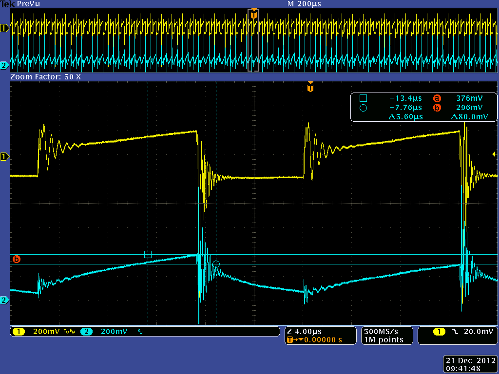
The pulse widths of each switching cycle are the same. I have noticed the start of the current ramps are diffrent. Which I think is why the peak value is diffrent as the di/dt of the ramps are the same. I think this behavior is basicaly due to the RC time constant of the filter network, its much higher than the switching cycle time (clock frequency of 46Khz)

The PSU works well and this is not affecting operation but I would like clarification on this please as to the reason it happens? 


Thank You

Alex

  • Alex,

    If you look at the waveform.  that is higher it also has a dc shift up by the same amount at the start of the pulse. Your problem may be board trace resistance and different current paths when opne switch is on verses when the other switch is on,

  • Hi John thanks for the reply

    I have solved this now. I thought exactly the same as you when going through tracking down this strange result. I even modifed the PCB to check this out this.

    Anyway I found out that for some reason when I connect two channels of my scope at the same time to the filtered and unfiltered nodes, it caused the low amplitured shown above. It's something to do with having the two ground scope clips connected to the same point. When only one channel and one ground clip is connected the signal looks normal, as soon as the other probe is clipped on problems occure. ???

    Any idea why? I have not really looked into it anymore since as all is well now. The scope is a Tek MSO4054 and is working fine, a good lesson learned!


    Alex 

  • Alex,

    That one i can't help with.