This thread has been locked.

If you have a related question, please click the "Ask a related question" button in the top right corner. The newly created question will be automatically linked to this question.

LM2267x as inverter - syncing it C-coupled

Other Parts Discussed in Thread: LM22670

Hi,

I have an application where I use the LM22670 as voltage inverter LM22670 Evaluation Board Inverting Topology and Application Notes (Rev. D).

Now I want to synchronize it through the SYNC pin. The above AN tells me something of using a level shifter to get a GND referenced sync signal. But this is a little  more comlicated than simply using a capacitor in series. With other simple switchers I already used this decoupling capacitor in series to the SYNC pin and this worked fine (at least for the LM2670 as voltage inverter (of course with a resistor to the ground pin) .

Question: is it possible to decouple the sync signal for the LM2267x also by using a capacitor? If yes, what pulldown resistor is recommended?

Many thanks in advance!

Wolfram

  • Hello Wolfram, 

    I have tried this in the past and it worked well:

    The ground referenced pulse signal gets AC-coupled and referenced to the negative rail. The 1k resistor should initialize the device in "sync" mode.

    Regards,
    Denislav 

  • Hey Denislav,

    many thanks for your fast response! Great - many thanks!

    Cheers,
    Wolfram

  • Hi alltogether,

    I want to reopen this topic again, since the solution above does not completely match my recommendation (as I found out now :-) )


    I want to start up with a free running, resistor-preset frequency (570kHz through 68k1). So the switcher must be able to startup without any external sync signal.

    After the FPGA has been loaded, the FPGA can provide a sync frequency overwriting the free running frequency (if necessary).

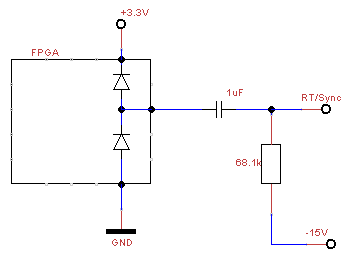
    Now I tested the depicted schematic with a 1uF for AC coupling and the 68k1 for presetting the free running frequency. When applying the input voltage the switcher begins to work, but NOT with the preset frequency but the free running unprogrammed frequency (that would be fine with me, but I don't understand it according to the datasheet)

    Even when the FPGA is at highZ at startup, it will be clamped to 0V and +3.3V resulting in charging currents and (for me) in an unpredictable behaviour of the switcher. According to the datasheet “ a much higher voltage than 0.8V” results in the need of external synchronization – so it would not startup on it’s own. But my measurements has shown: it’s starting up in free running mode (530kHz), but not in preset 570kHz. But it was synchronizable (that’s what I assume – my setup was too lousy to generate a clean external sync referred to -15V)

    So my question is in concrete: do you have a “small” level shifting application keeping giving the chance to work with a preset frequency which can be synchronized on demand (by a 0 …. 3.3V signal)?

    Many thanks in advance!

    Wolf