This thread has been locked.

If you have a related question, please click the "Ask a related question" button in the top right corner. The newly created question will be automatically linked to this question.

UCD9090 - UCD90SEQ48EVM-560

Other Parts Discussed in Thread: UCD9090, UCD90120A, UCD90160

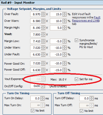
My customer has been battling my way through this UCD9090 part and it's GUI.  they have come across a situation that I have so far not been able to resolve.  They have assigned a 0.025 divider to MON11.  When they enter the scale factor, or anything else lower than about 0.112, the reading just instantly drops to zero.  Their MON8 connects to a divider for 12 V, uses 0.110 as a factor, and works perfectly.


They are using software version 1.8.318, dated April 9.  Any ideas?

  • Hi Rob,

    Could you provide the xml file of the customer's configuration?

    Regards,

    Dan

  • Hi Rob,

    I do not see MON11 assigned in the XML file.  Are they trying to monitor an 11th rail?  The UCD9090 is capable of sequencing and monitoring up to 10 rails.  If they want to do more than 10 rails, they can look at other UCD90XXX parts.  The UCD90120A can do up to 12 rails and the UCD90160 can do up to 16.

    Also, it looks like rail #7 might be misspelled.  It is written as v5p8 under Rail Name but Vout is set to 5V.   

    Regards,

    Dan

  • Sorry the previous file had been updated - here it is:

    4645.UCD9090 @ Address 101d changes to Rail 9.xml

  • Hi Rob,

    MON11 has an input range of 0.2V to 2.5V while MON1-10 have ranges 0V-2.5V.  Is there any reason your customer needs to use such a small Vout Scale Monitor?  For 7.8V, they could use a scalar in the range of 0.2 to 0.25.

    Regards,

    Dan 

  • Yes, that's the point.  The divider input is actually up to about 50V, thus the small desired ratio.  Our hardware has 0.0254 ratio. But, once I drop below a certain level, the reading suddenly becomes zero.  So, I'm using the smallest value that does not wreck the reading.  That gives me a reading of about 7.8 volts.

  • Have you tried changing the Vout Exponent to -9 or -8?

  • Customer update:


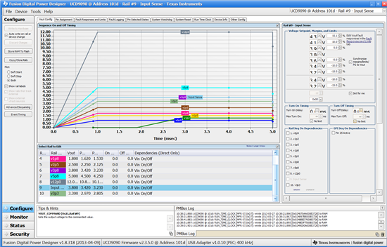
    By the way, what version GUI is this from?  My GUI is totally messed up compared to the one posted. Mine has labels missing and numbers unreadable.


    When I update the exponent, I see the Max change.  I write the parameters to hardware, and I STILL see zero volts on the monitor.  Clearly, there is something either wrong, or a misunderstanding.


    Also it seems that you get different results depending on what route you take to your destination.


    We have pulled rail #9 from the global power good signal and using it to wag a GPO.  It turns out that it's actually Power Good Off that makes the line switch.  So what, then, do the Margin/Warn/Fault limits do?  Nothing!  would be great for Rail #9.  It seems that crossing those thresholds on that rail no longer flip the power good or system resets, which is the desired situation.  I just want to know what else might happen when Rail #9 falls.

  • Rob,

    The image was taken from v1.8.319.  I also tried opening it with v1.8.318 and got the same results.  Could you provide a screenshot of your GUI with Rail 9?

    I am not sure why you are getting zero volts on the monitor.  To get to the bottom of this, could you provide the schematic and the most up to date xml configuration?  If you do not want to post it to the forum, you can send it to me directly.

    The margin limits are set so you can margin your voltage rail high or low during a power-up.  Based on the xml file, it does not look like there is any margining because there are no margin PWM pins assigned.  I also do not see anything set in the "Fault Responses and Limits" tab, so the sequencer is not going to take any action when a fault occurs.  It will, however, log a UV fault when Rail #9 falls below Power Good Off since Power Good Off is set at the same value as Under Fault.  

    Regards,

    Dan

  • It's seeming that some of the matters boil down to lack of user competency [fault vs warn vs power good].  Other problems are unexplained.  Like I was saying, it seems that the monitor function works fine now, but I had to take a different route to the final destination.  So, presently, my monitor is monitoring fine.  However, the GUI is not displaying correctly, and that makes it difficult to use and understand.  I wonder if there is a problem running on Windows 7.  I could send part of our schematic, but it wouldn't show very much, just a bunch of resistor dividers.

    Correct in that there is no margining.  In fact, there is a lot of functionality that either hasn't been implemented yet or won't be by design.  I could also update the most current config file.

    If there was a concise explanation regarding fault vs warn vs power good, that would be a big help.  Is there a manual that I'm missing?

    Presently, most outstanding:

    1. Why does my GUI look so poor?

    I want to make sure I understand which threshold do what and make sure that low voltage on MON11 (rail #9) only wags the GPIO and nothing else. 

  • There should not be any compatibility issues with Windows 7 (my system runs on Windows 7).  Can you please provide some screenshots of your GUI where you see the issues?  Have you tried installing the newer version of the GUI - v1.8.325?  

    The top of page 20 of the data sheet discusses warnings and faults.  It states:

    FAULT RESPONSES AND ALERT PROCESSING
    Device monitors that the rail stays within a window of normal operation. There are two programmable warning
    levels (under and over) and two programmable fault levels (under and over). When any monitored voltage goes
    outside of the warning or fault window, the PMBALERT# pin is asserted immediately, and the appropriate bits are
    set in the PMBus status registers (see Figure 7). Detailed descriptions of the status registers are provided in the
    UCD90xxx Sequencer and System Health Controller PMBus Command Reference and the PMBus Specification.

    And on page 21:

    Warning Actions
    — Immediately assert the PMBALERT# pin
    — Status bit is flagged
    — Assert a GPIO pin (optional)
    — Warnings are not logged to flash

    A number of fault response options can be chosen from:

    Fault Responses

    — Continue Without Interruption: Flag the fault and take no action  (This is selected so far)
    — Shut Down Immediately: Shut down the faulted rail immediately and restart according to the rail
    configuration
    — Shut Down using TOFF_DELAY: If a fault occurs on a rail, exhaust whatever retries are
    configured. If the rail does not come back, schedule the shutdown of this rail and all
    fault-shutdown slaves. All selected rails, including the faulty rail, are sequenced off according to
    their sequence-off dependencies and T_OFF_DELAY times. If Do Not Restart is selected, then
    sequence off all selected rails when the fault is detected.

    Restart

    — Do Not Restart: Do not attempt to restart a faulted rail after it has been shut down. (This is selected so far)
    — Restart Up To N Times: Attempt to restart a faulted rail up to 14 times after it has been shut down.
    The time between restarts is measured between when the rail enable pin is deasserted (after any
    glitch filtering and turn-off delay times, if configured to observe them) and then reasserted. It can
    be set between 0 and 1275 ms in 5-ms increments.
    — Restart Continuously: Same as Restart Up To N Times except that the device continues to restart
    until the fault goes away, it is commanded off by the specified combination of PMBus
    OPERATION command and PMBUS_CNTRL pin status, the device is reset, or power is removed
    from the device.
    — Shut Down Rails and Sequence On (Re-sequence): Shut down selected rails immediately or after
    continue-operation time is reached and then sequence-on those rails using sequence-on
    dependencies and T_ON_DELAY times.

    The system you configured is choosing to ignore faults, but still log them.  Power Good does not directly trigger faults in the system.  You could - hypothetically - set Power Good Off to be above the Under Fault, so the controller would say the rail is out of regulation, but would not register it as a UV Fault.  PGood is more important for setting up dependencies - like if you want rails to turn on or turn off in a particular order.  PGoods of particular or multiple rails can be tied to Logic Controlled GPO pins like you have in your configuration.  This can alert other parts of the system - a host processor for example - if the rails are out of regulation.

    I do not see any dependencies on Rail 9 from the file you gave me, so if the rail were to go below 15% of its set value, a UV fault would be logged (but no fault response would take place) and the PGood for Rail 9 tied to Pin 26 (GPIO17) would flip stating the rail is out of regulation.

  • Screenshot of GUI:

  • I have not seen this type of issue before.  It might be related more to some of your settings of Windows - resolution, text size, etc.  What version of Windows 7 are you using?  You could also try uninstalling and re-installing the software.