This thread has been locked.

If you have a related question, please click the "Ask a related question" button in the top right corner. The newly created question will be automatically linked to this question.

TPS40304 running but doesn't regulate the output

Other Parts Discussed in Thread: TPS40304

Hi,

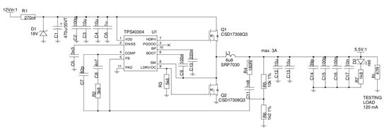
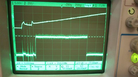
I'm working on the design of the DCDC regulator 12 V / 5,5 V 3 A  with controller TPS40304.  We assembled the prototype pcb, the problem is, that controller is running, switching the MOSFETs, but doesn't regulate the output. For measuring and testing, small resistive load of 120 mA (47 ohms) was connected to the output. The MOSFETs are switched noncontinuously with groups of 600 kHz pulses every about 2 ms. So there isn't constant DC voltage at the output, output voltage has the characteristics of discharging capacitor every 2 ms. I measured and took a shot of signals on all pins of controller from the startup (see below). Has someone idea, why the controller doesn't regulate the output? We already changed the MOSFETs and controller for the new ones with the same result.

Schematic

The upper trace is the input voltage on all images, the lower trace is the signal on measured pin:

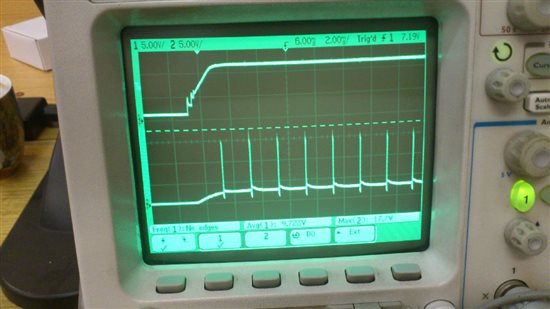
Pin 2 - EN/SS

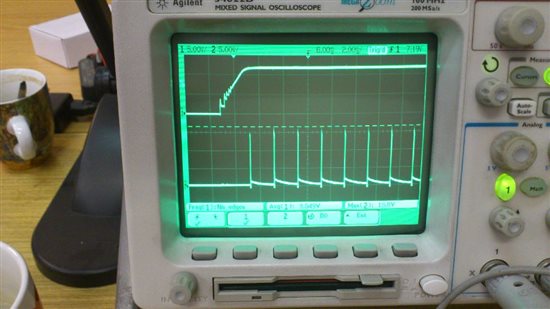
Pin 4 - COMP

Pin 4 - COMP - detail of one pulse

Pin 5 - FB

Pin 6 - BOOT

Pin 6 - BOOT - detail of group of pulses

Pin 6 - BOOT - detail of single pulses

Pin 7 - HDRV

Pin 7 - HDRV - detail of group of pulses


Pin 7 - HDRV - detail of single pulses

Pin 8 - SW

Pin 8 - SW - detail of group o pulses

Pin 8 - SW - detail of single pulses

Pin 9 - LDRV

Pin 9 - LDRV - detail of group of pulses

Pin 9 - LDRV - detail of single pulses

Pin 10 - BP

Output voltage

  • From the look of your waveforms, I think you are triggering hiccup mode OCP.  I would look at your calibration voltages during start up. Also it seems you have some dc offset on the ENSS pin.  It needs to go below 270 mV to ensure a restart.

  • What is the reason for the OCP triggering with such a small load (120 mA) and with this type of MOSFET (about 9 miliohm)?  Which calibration voltages do you mean? On ENSS pin, there can be seen the calibration after power on at 1,3 V for about 2 ms. The DC voltage is due to the short time of power off, when I measured the waveforms on the pins after startup. Is there a need for the ENSS pin voltage to go below 270 mV to ensure a restart even if the input voltage goes to the zero (manuall shorting of the input capacitor after power off)?

  • I made a couple fo measurements focused on the OCP mode triggering.

    The startup OCP level calibration seems right, OCP voltage level is about 57 mV (5k6 resistor)

    Waveforms on SW pin 8:

    The whole group of pulses

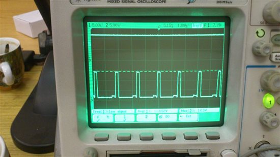
    The detail of the low MOSFET switching, voltage drop is about a few mV, so in the limit

    Detail of the last 6 pulses in the group of pulses - the higher voltage level maximum drop is about 750 mV, it seem that the HDRV driver cannont full open the higher MOSFET at the end

    Waveforms on HDRV pin 7:

    It confirms the previous waveform from SW pin, for some unknow reason the voltage on HDRV gradually falls from 14,4 V to the minimum od 12,9 V before the controller stops the switching

    The whole group of pulses

    The detailed upper part - the maximums of pulses, there is a voltage drop of about 1,3 V at the end

    The detail of the last 6 pulses - there can be seen the slowing down of the rising edge

    HDRV voltage relative to the input voltage - upper MOSFET drain, HDRV is gradually falling, driver cannot open the MOSFET

    The SW voltage compared to the input voltage

    Comparing the BOOT to SW voltage - when the upper MOSFET is ON, both voltages are the same

    Has someone the idea why the high MOSFET drivers gradually fails to switch?