This thread has been locked.

If you have a related question, please click the "Ask a related question" button in the top right corner. The newly created question will be automatically linked to this question.

LM2675 thermal shutdown - why is it getting hot?

Other Parts Discussed in Thread: LM2765

Hi Ti,

Please could you help me get to the bootom of this mystery?

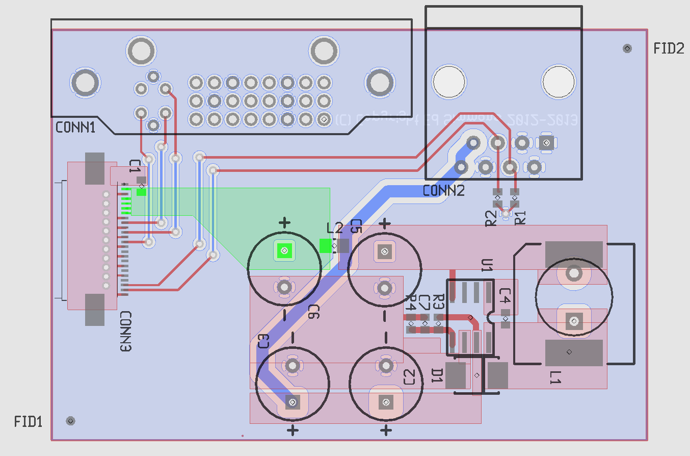
I've made a small number of specialist boards that carry an LM2765 12v fixed output switching regulator. We have followed the datasheet and used the recommended layout for the regulator on the PCB.

We've verified all the parts are correct values etc but the LM2765 goes into thermal shutdown very soon after applying power.

Our design is 24v Vin, 12v out, 100uH inductor (we have tried swapping different inductors of the same value but different constructions with wildly differeing results) and a load current of ave 300mA & peak of 450mA.

Please can someone offer me some advice on fixing this issue?

Thanks & best regards.

Ed

  • Be sure that the DAP is well soldered down to the ground plane and you have enough ground

    plane for heatsinking.  Take a look at app note SNOA401 and SNVA021C and SNVA054C and SLUP230.

    FD


  • Thanks for your reply Frank,

    The part we're using is the 8 pin SOIC package, with no pad on the underside of the IC. We have taken the PCB layout as directed in the datasheet and used it verbatim. The datasheet states that the IC requires no heatsinking beyond the recommended layout of PCB traces.

    We have tried a number of different inductors and replaced the boost cap all with similar results, the temperature rapidly climbs and then the IC shuts off. Before shutting off, the IC is working fine providing the desired 12v output.

    I'm relatively new to switchmode PSUs (hence choosing the simple switcher for this product - the specs seemed perfect) so please could someone help me understand why the part is not working as expected? I'm operating the device well within its limits and I'm keen to find the reason for overheating.

    thanks,

    Ed

  • From what you have said the converter should work as expected.

    1.  What is your ambient temperature?

    2.  Does the inductor have an unusualy high resistance?

    3.  Is the bootstrap capacitor correct?

    4.  Is something else on the board heating up the coverter?  LIke the wrong type of diode?

    Send us your schematic and layout and we will look at this more.

    FD

  • Thanks Frank,

    1. Ambient is around 20 degrees - the board is small it is just an adaptor between various connections and also carries the switching supply
    2. The inductors we have tried are all low resistance - the original choice was an SMT shielded inductor with a resistance of 0.15R - value 100uH as per the selection tables in the datasheet.
    3. The bootstrap cap (c4) is an 0603 50v 10nF X7R. Is this too small physically? Should I choose a larger package? I tried to determine if this cap was being discharged, but I think it's ok.
    4. The diode I chose is this: http://uk.rs-online.com/web/p/rectifier-schottky-diodes/6291426 - it doesn't seem to be the cause of the heat (I can put my finger on it when the IC is too hot to touch)

    Do pins 2 and 3 matter? I've looked at my layout and it doesn't ground pins 2 and 3, they're not mentioned in the schematics but are shown as grounded in the example layout.

    Thanks for your help...

    Best regards,

    Ed

  • Hi,
    1. try more inductance 180µH ..220µH, the layout looks good
    2. is  C2 and C3 a low ESR Type
    3. sorry, is it a LM2675-12 or ADJ..
    4. Pin 2 and 3 n.c. is ok
    5. C5 and C6 are placed correct? Polarity?
    6. measure on Pin6, is there a stable PWM with load
    7. simulate your design with your components at webench, stable?
    8. input voltage stable?

    Best regards
    Martin

  • Hi Martin,

    Thanks... helpful advice...

    1. I will try this and report back.
    2. Yes, all the through hole caps are low ESR quality electrolytics, the power noise (input and output) is a few mV RMS only.
    3. LM2675-12 - the resistor divider and cap is to provide a delayed start to limit the inrush of the system as a whole, this board is a small component of a larger system. This is working as expected, enable pin rises to 4v when supply is 24v.
    4. Great...
    5. Yes, correctly installed caps and the right rating.
    6. Pin 6 is GND, did you mean pin 8? I've observed the switching waveform, but not for long enough to get a decent scope shot of it. I will try this when I get the chance to keep it switched on for more than a few seconds.
    7. I tried this, the issue I'm facing is that the reality doesn't tie up with simulation.
    8. Input voltage is stable, 24v from a bench supply, confirmed using bench meter and scope...

    Thanks for your help.

    Ed

  • Pins 2 and 3 should be connected to the ground plane.  This will help with the

    heatsinking.  Also, try to get as much ground plane as possible.

    FD


  • Hi,

    Following are my suggestions,

    1. Please ensure that the switching regulator you ordered & switching regulator in the board is same (can be ensured by checking TOP side marking of device with top side marking provided in TI's web site) - even signle digit variation may make big differnece in part

    2. Seems you used general purpose diode, try to use rectifier diode

    3. Ensure inductor is correctly soldered, if it is 90 degree rotated & soldered it would get shorted.


    Thanks,

    Bala

  • Hi Bala, and everyone else who has helped.

    Your message was well timed - I have just swapped the diode for a better schottky  and found it works very well.

    Thanks for everyone's input, I am pleased this is resolved.

    Best regards,

    Ed

  • Hi Ed,

    You are welcome..

    yesterday i though to type schottky diode (fast r.recovery) instead of general purpose diode, uncertainly a phone call diverted me  to type "rectifier diode" which has mentioned in your Vishay diode datasheet :-(. However you sparked up the point. Great.

    sometime back I had the same case & resolved it. but in my case diode got opened first.

    Thanks,

    Bala.