This thread has been locked.

If you have a related question, please click the "Ask a related question" button in the top right corner. The newly created question will be automatically linked to this question.

LM2842 burning up with 32.8volts on the input.

Other Parts Discussed in Thread: LM2842

This is the first run of these boards, (we made 20 prototypes) What happened was we tested all 20 boards with Vin of the lm2842 at +12Volts all 20 boards worked.The customer said they wanted it tested at +36Volts as that’s what they will be using for  Vin. My bench power supply could not go that high so I was using +32.8volts instead of +36V and retested the boards

4 of the boards that previously worked at +12V had the LM2842 instantly go up in smoke and flames when Vin was +32.8V. the other 16 board work correctly.

The LM2842 is rated for working up to 42V with a 45V max Input , so the 32-36V is clearly well within the operating spec of this device.It’s internally compensated so you can’t make a mistake there, and if it operated at +12Vin, then there clearly shouldn’t be an over-current issue (since Vout and the Load should not have changed at all).  

we need some help determining why the LM2842 burned up and dammaged 4 out of 20 boards.

FYI, Pin 4 the shutdown pin was connected to Vin for this test.

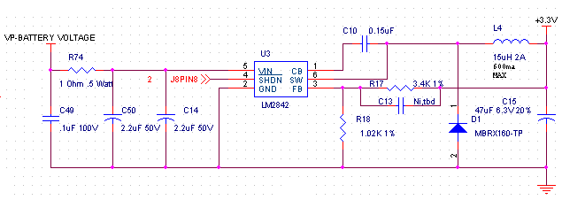
below is a picture of the smoked board (U3 the Lm2842 is burned ) and the power supply part of our schematic

After the Lm2842 burned we remove the Lm2842 and the board now measures as shorted on the +3.3V output to GND (.03ohms) we think this is because when the LM2842 failed it damaged the TMS320F28032PNS  that we have on the board. before applying the +32,8V the boards did not measure as shorted, we acutally measured across C15 the 47uf output cap before applying power the first time (first time turn on we used +12V as Vin ) and all the board measured about 4.3K  across c15, (measure with the board off)

before  Testiing at +32.8V with a Vin of +12V applied , All the boards turned on and we measured the proper output of about +3.3V our lowest reading was +3.28V and our highest was +3.31V

So this problem has us puzzled.


  • How are you applying the 32V ?

    Are you slowly ramping to that value or "hot" plugging ??

    It could be that you are getting a resonant over-voltage from the long power supply leads and the ceramic input capacitor.  You can try to connect an electrolytic cap across the input and try the tests again; the ESR of this cap will help to damp the over-voltage.

    In general it looks like your input cap of 2.2uF is too small.

    FD

  • Hello we were hot plugging

    Our theory is the ceramic input capacitor C14 combined with stray inductance in series with the power source formed an under damped tank circuit, and the voltage at the VIN pin of the LM2842 may have started to ring to a higher than nominal Input voltage, possibly exceeding the LM2842’s rating and damaging the part.

    so we put our Oscilloscope across C14,  what we found was hot plugging was creating a transient that reached 76.8V

    so we modified the circuit , by adding  r74, C49 , C50

    The 1Ω resistor was added in series with the input to eliminate the voltage overshoot (it also reduces the peak input current). The 0.1μF capacitor improves high frequency filtering. This solution is smaller and less expensive than adding a electrolytic capacitor.

    This looked lke it was fixing the problem but we burned up another LM2842 today.

    the highest transient we saw when testing this change was ~ 47V which is pretty much the max input for the lm2842

    Sorry I don't have a picture handy to post.

    I have not yet tested increasing the resistor value but I am thinking that , Icreasing the resistor value would be better than adding more input capacitance? (FYI, we don't want to use a big Electrolytic cap which would be the easy fix.)

    Next question could the capacitance of our Oscilloscope probe be lowering the transient shown on Oscilloscope . I.e could the Transient really be a lot higher than we think.  I ask this as after making the above fix , we turned the regulator on and of multiple times with no problems then later in the day we went to do some more testing , we burn up the LM2842 (no scope probe on the out put when it burned up.)

    Al

  • Hi Alfred,

    For such a high Input voltage, be sure to use the slower version of the part LM2842(X). Based on minimum on time of 100ns and a duty factor of roughly 10% (3.3V/36V) for 550kHz that translates to 1.8usecs period or 180nsecs on time approaches the max on-time limit of the part.

    On time will definitely be violated when using the faster part at this voltage ratio.

    Thanks,
    Anston 

  • Hello Anston

    Thanks for the heads up on the using the slower version

    FYI, we have been using the slower LM2842XMK-ADJL/NOPB part  .

    That said, we think we have fixed the issue. heres our current schematic with a snubber added.


    and heres what the transient now looks like with a +36V input (CH1 of the scope was measuring across c14)

    Al