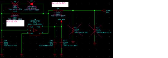
I am using the attached circuit below to generate a clock at about 800K to sync two LMZ22003’s together.
The allowed synchronization frequency range is 650kHz to 950 kHz. The typical input threshold is 1.4V transition
level. Ideally the input clock should overdrive the threshold by a factor of 2, so direct drive from 3.3V logic via a
1.5kΩ Thevenin source resistance is recommended.
So originally I had R4, R5, D2 AND R3 installed. The purpose for the D2 and R3 was having a clock with the lower than 50% duty cycle, but according to the data sheet:
Sync d.c. Synchronization duty cycle range 15 50(typ) 85 %
I removed D2 and R3 to set the duty cycle at 50%. The purpose for the R5 was to lower the 5V pulse amplitude to have more margin at the sync pin since it has a 5.5V max spec. I noticed a square wave pulse at 800k at U4 pin 4 (Left side of R4) which is the expected clock. However, looking at just the other side of R4 (2k resistor) there is a distorted signal like a Ramp instead of the square wave. I removed R5 and replaced R4 with a jumper. Now I have the expected clock (a square wave at 5V amplitude and 50% duty cycle) at the SYNC pin which is expected. However, this implementation disagrees with what is recommended in the data sheet as this is not direct drive via a 1.5K Thevenin source resistance. So I have the following questions:
1) Have I misunderstood what have been stated in the data sheet? If yes, what
2) Will my implementation direct drive from a 5v LOGIC via a very low impedance hurts the SYNC? If yes, do you have any suggestions?
3) What is the reason for the distortion when I drive the SYNC via a 2k RESISTOR? Is the SYNC pin a highZ?
4) Is there any way to check if the two LMZ’S ARE IN SYNC other than looking at their output ripples ?
5) Would buffering the oscillator output keep my pulse from affecting the LMZ sync?
Thank you,
Adam


