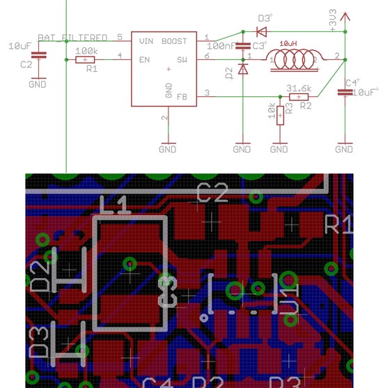
I am using the LM2734ZMK for converting 7-13V battery voltage to 3.3V for powering a microcontroller. When I power my board with a lab power supply (with fairly long wires), everything works as expected. However, if I plug in a 3-cell lithium-polymer cell (20C discharge capacity, capable of delivering tens of Amps), the LM2734 fails to start up cleanly. My Microcontroller gets very hot, I suspect because I have a separate LDO to power the analog parts (possibly there is current flowing through the ESD diodes to the digital rail). The LDO is enabled by the digital rail, so in principle it shouldn't activate too early (but it is possible that a non-stable digital rail will already enable it).
If I first plug in the lab power supply to let it start cleanly, and then plug in the battery and unplug the lab power supply, the circuit remains stable - the problem only happens at startup. Once stable, it will run indefinitely on battery as well.
I attached the relevant parts of the schematic and board layout. As far as I can tell I followed all the design recommendations. I have a 100uF tantalum capacitor on the input rail (called BAT_FILTERED), and a 10uF ceramic close to the switcher. The output capacitor (after the inductor) is also a 10uF ceramic.
Checking the input rail with the oscilloscope shows no significant difference, other than the rise time being much quicker (the battery delivers a lot more current, so the input capacitor gets charged more quickly).
I tried the following:
- connecting a 1-Ohm Resistor in series with the battery cable fixes the problem
- connecting a 100nF capacitor between the enable pin and GND to delay startup fixes the problem most of the time, however if the board is unplugged and plugged in again quickly, the enable delay is still charged and the problem occurs again.
Is this a known problem? I don't really understand why this is happening, I would have expected the opposite (problems with the low-current supply rather than the battery). What should I do to fix it in the next design iteration? I don't want a series resistor on the input if I can avoid it.


