


This question is broader than the LM2841, but let me explain.
I am trying to usher an automotive-qualified buck converter based on the LM2841 through a customer-proprietary EMC approval that is almost identical to CISPR 25. Our early design failed the section on "conducted disturbances on power input terminals" at the 550 kHz PWM frequency of the LM2841, so we added an LC filter in front, resulting in the following schematic:

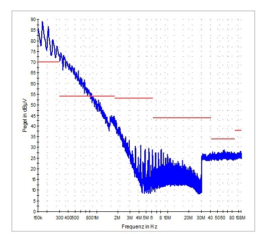
This change adequately suppressed the 550 kHz component, but added a broadband disturbance, beginning at a frequency below the bottom threshold of our instrumentation and continuing up to around 4 MHz.
After a bit of experimentation, we discovered that rotating either L302 or L301 by 180° on the board would knock the broadband disturbance down by 30 dB or so--not enough to eliminate it, but enough to pass the test. We suspect that there is a magnetic coupling path between L301 and L302 (which are 'shielded' parts, but separated by only around 8 mm on the board) that closes a loop and induces resonance within the regulator circuit itself. We have never been able to see this oscillation on a scope: it only shows up in the spectrum analyzer output.
The tight spacing is customer-imposed. The noisy inductors must be next to something.
The problem is, when I talk to the inductor manufacturers:
- The more co-operative ones will tell me whether a dot located over a pin on the package indicates the 'beginning' or the 'end' of the coil.
- Other manufacturers do not even bother with the dot.
- Nobody will tell me which way the coil is wound, provide a drawing of the shield, or even document the location of the air gap.
I am admittedly a newbie in the automotive EMC field, but it seems to me I can't even begin to address the problems of fields emitted by these devices with such sketchy info.
Or am I barking up the wrong tree?
I also wonder whether the regulator is underloaded (40 mA), but can’t find a minimum power spec on the data sheet.
All advice appreciated.