This thread has been locked.

If you have a related question, please click the "Ask a related question" button in the top right corner. The newly created question will be automatically linked to this question.

LM3409 several switching cycles in freewheeling period

Other Parts Discussed in Thread: LM3409, LM3405

Hi guys,


I am working on a project, using the LM3409 buck converter. 

The constraints are:
Vin 12 - 40V, Vout: 9V, Iout: 1-5A, frequency: approx. 500kHz.
Shunt: 47m Ohms
Coff: 2nF, Roff: 220 - 10k Ohms.

I simulated the project, and everything was fine. 
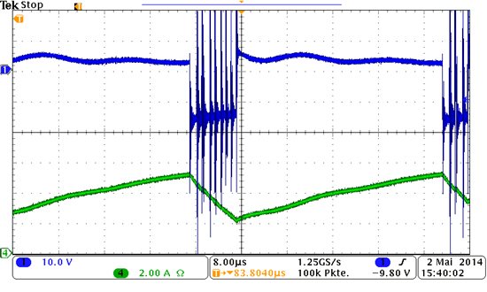
When I built it, I saw that there are several very short on- and off- switching states within one free-wheeling cycle. The time between them is approximately the off-time.

Now I red the datasheet, and that says, that the LM3405 switches the + and - comparator inputs with every cycle - leading to an offset of 24mV.
-> the current has to decrease by more than 0.5A before the next switching cycle - if a shunt of 47m Ohms is used.

The problem is still there, if I make sure, that the current deccreases more than 0.5A before the off-time ends.


This is a problem, because it leads to a very high inductor current ripple and to many switching cycles, which leads to a thermal problem of the switch.

If the current is reduced, or the off-time is reduced, the switching cycles within one free-wheeling period become less.

You can see the volatage and the current in the inductor in the picture attatched.

Does someone have an idea where this problem might come from and what could be done about it?
Did anyone have a similar problem?

Thanks,

Philipp 

  • Hello Philipp,

    May I ask the test conditions under which you got the screen cap?
     Are you using a 47m Ohm sensing resistor(Rsns) and what is your inductor value?

    Normally the inductor current will look like the one in figure 26 on pg.11 of the data sheet. There is also a minimum inductor current ripple requirement. The Roff and Coff will help to define the inductor current ripple.

    Best regards,

    Victor

  • Hi Victor,

    thanks for your reply.

    Yes I am using a 47m Ohms sensing resistor.

    Roff and Coff are variable, but in this case the off-time was approx. 1µs.

    The coil is 33µH.

    The inductor current should be the maximum (5 A).

    The load were diodes with a forward voltage of 9V. The input voltage was 14V.

    If I use a Rsns of 200m Ohms, the converter behaves similar, but it has only one such switching cycle in the freewheeling period.

    Do you need some more information? Any idea, why this could happen?

    Thanks,

    Philipp

  • Hi Philipp,

    Thanks for the info.

    Please note that your parameters should full fill below equations under all situations.

     (I assume your Vadj here is 1.24V )

    Your current waveform may look like this.

    I think the regulator should be working properly after you change Rsns to 200m Ohm (if your target LED current is about 1.1A).

    One thing I noticed is that your input voltage and output current have a large variation. Since LM3409 is constant off-time control, Vin will only affect the switching frequency and the peak inductor current is the maximum LED current + half of inductor current ripple.

    Best regards,

    Victor

  • Hi Victor,

    Thank you very much for your reply. 

    I do fulfill these conditions. But I found the error. I built up the design on a stripboard, not a PCB, and I got some EMC problems.

    I arranged some components slightly differnt. Now it works like it looks like your picture shows it. 

    Best regards,

    Philipp