This thread has been locked.

If you have a related question, please click the "Ask a related question" button in the top right corner. The newly created question will be automatically linked to this question.

TPS 5403

Other Parts Discussed in Thread: TPS5403

Hi TI,

Recently, I would like to use TPS5403 to regulate voltage from "Solar Power (18V) or voltage from Lithium Ion battery (7.2V)" to 3.3V.

Following are the questions:

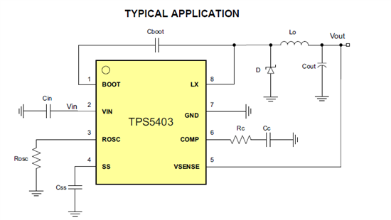
1. How to determine the switching frequency? this is required to choose for ROSC value.

2. I found this information about VSENSE connection, "For VIN<6.5V, in order to maintain a stable 3.3V output voltage, a minimum 15-mA current is need to apply at the output."

For this, do we need to connect resistor from VOUT to VSENSE? if so, how is the calculation?

3. How to determine Rc and Cc?

4. How to choose for inductor value if our VIN is varied from 4.5V to 18V?

Thanks.

Lee

  • 1.  It is up to you to select the switching frequency.  It is an engineering option.  In general, lower frequency gives better efficiency and larger size, higher frequency gives lower efficiency at a smaller size.  500 kHz is a good compromise.

    2. You would connect a resistor from Vout to GND.  3.3/015 = 220 ohm.  If you have some minimum load anyway, you can increase the value to 3.3 / (.015 - min load) = R.

    3.  The datasheet is not very good for that part.  They do not include that info. Normally I recommend pspice modeling to derive the compensation components.  There is no model available either, so the next best approach is to make an educated guess then measure the loop and adjust.  I van help you with that but you need to select the output filter components first.

    4.  You can use typical Vin or maximum Vin to calculate L.  How tightly do you need to control the ripple current?  It will be worst case at Vin max, but that drives your inductor value up.  It is an engineering trade off you have to make.

  • Hello John,

    Regarding your answer to question 3 about the compensation component values, would you be able to provide a good number/guess for Rc and Cc for our purpose. We have selected our output filter components as L = 38 uH and Cout = 5 uF. Just for reference input capacitance is Cin = 10 uF.

    I will appreciate your help in this.

    Thanks,
    Dhruv
  • 5 uF seems extremely low value for output filter capacitor.  Maybe you can start with 22 uF?

  • JohnTucker said:

    5 uF seems extremely low value for output filter capacitor.  Maybe you can start with 22 uF?

    Thanks John for the reply. For our use case, the delta I_out (output current) is 0.7 A which is low. Due to this the required output filter capacitance is lower. A 10 uF (not 5 uF - that was a typo)  would work as per calculations based on the datasheet.  

    Could you help me with the compensation components based on L = 38 uH and Cout = 10 uF.

    Thanks,

    Dhruv