This thread has been locked.

If you have a related question, please click the "Ask a related question" button in the top right corner. The newly created question will be automatically linked to this question.

High Load switches inductive load

Other Parts Discussed in Thread: TPS22929D, TPS27082L, TPS27081A, BQ25504

Hi !

I am planning to use one of the following devices 

TPS22929D

TPS27082L

TPS27081A

However, my application will have an inductive load which is different from the datasheet typical applications where it is used with a capacitive load. The inductive load is a boost converter. which will be the consequences regarding the slew rate and inrush current ?

thanks! 

  • Hello German Rojas,

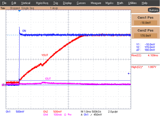
    I took a TPS22929D and connected its output to a TPS69017 (Boost Converter). 

    If the boost converter has its enable turned off when the load switch is turned on (recommended), then the load switch output behaves as expected.

    If the enable of the boost converter is connected to its input, then the following can be seen at the output of the load switch.

    The output of the TPS22929D slews normally until the turn on threshold for the boost converter is reached (~0.85V).  When the boost converter is turned on, the current jumps up, and when the part finishes turning on, the load switch continues to slew normally.  The whole time there is no drop on the input of the load switch.

    Does this answer your questions about the inrush current and slew rate?


    Alek Kaknevicius

  • Hi Alek 

    Thanks for your answer

    the inductive load that I mentioned in my previous plot is specifically the BQ25504's VIN pin, This IC don't have a enable pin, so in this case the boost is switching everytime.

    However, My main doubt is that the datasheet's equation for the inrush current, which is directly related to the slew rate, has C_load as a parameter but there is not a capacitor load at the BQ25504's VIN pin , what will happen in this case with the Vout and Iout waveform ?

    Thanks!

  • Hi German Rojas,

    Alek will soon reply back to your query.

    Regards
    Ankush

  • Hi German Rojas,

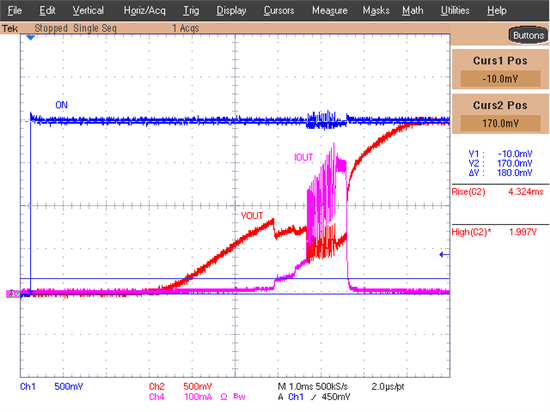
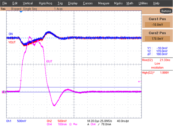
    The second scope shot I posted above was the load switch turning ON with the boost converter already ON.  I believe this is the same setup you are describing.  To answer your question, if no capacitance is used, then the equation in the datasheet for inrush current and slew rate cannot be reliably used when the boost converter ON threshold is reached.  In the scope shot, the current jumps about 175mA within a short period of time and the normal slew of the load switch is disrupted.  To compare, below is a screenshot of the boost converter turning ON with the load switch already having been turned ON.

    Here the inrush current is around 400mA.  This is 100mA more than the boost converter and load switch being enabled at the same time.  So while the inrush current is reduced when using a load switch, both the slew rate and inrush current cannot be reliably estimated using the slew rate equation in this situation.

    Let me know if I can answer anything else.


    -Alek