This thread has been locked.

If you have a related question, please click the "Ask a related question" button in the top right corner. The newly created question will be automatically linked to this question.

LM3405 COULDNT DRIVE 1A ?

Other Parts Discussed in Thread: LM3405

Hi,

I am trying to drive constant 1A current using LM3405 connected to a single OSRAM IR LED "SFH 4715".

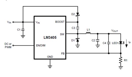
Below is the circuit using which I am trying to achieve the above:

Setup I used:

  1. VIN = 5V

  2. EN/DIM = TIED to 5V VIN DIRECTLY

  3. R1 = 0.2 ohms (Tolerance unknown)

  4. L1 = 10uH, 5.8A (Manf. part no: B82477P4103M)

  5. D1 = Manf. part no "PMEG3015EH,115"

  6. D2 = 1N4148

  7. C1 = 10uF/6.3V (X5R or X7R not sure, bought from local market)

  8. C2 = 1uF, 10V (X5R or X7R not sure, bought from local market)

  9. C3 = 0.01uF/16V (X5R or X7R not sure, bought from local market)

  10. C4 = 1uF, 10V (X5R or X7R not sure, bought from local market)


My Observations:

@ SW pin = getting ~90% duty cycle of 1.6MHz PWM output.

@ VOUT = 2.5V

@ VFB = ~0.2V

But the Current consumption of this setup is only ~200mA.


The OSRAM IR LED part I am using has forward current = 1A and forward voltage max 2.8V.

For you reference I am attaching the IR LEDs datasheet.

7180.OSRAM IR LED DATASHEET.pdf

I would like to know what could be limiting the output current to 200mA instead of giving out 1A.

Datasheet says, Iout = Vfb/R1 = ~0.2V/0.2ohms = ~1A. 

L1 Inductor am using has good current capacity (5A). So this should not be a problem ?


I tried debugging this in following methods:

1. Check how much current the OSRAM LED takes, IF CONNECTED DIRECTLY TO POWER SUPPLY :

    Varied the forward voltage from 2V to 4V. When >3V the LED started drawing huge current.

    Does this mean, its forward voltage(max 2.8V) as claimed in its datasheet is wrong ?

    Or did the LED got damaged and thus it was drawing huge current ?


2. Tried connecting another IR LED (OSRAM) in parallel to this. Still NO CHANGE. Vout = 2.5V and Iout = ~200mA.


It would be very helpful if someone could clarify.


Thanks and regards,

Karthik

+91-9944980621


  • Hi,

    You should not get 90% duty cycle for a 2.5V output with 5V input. Please check if there is soldering issue and the feedback resistor value is correct.

    Larger inductor value will lower the inductor ripple current which is OK/good in this case. Not sure if the issue is caused LED, but you may just use a 3.3V white LED to prove it.

    Best regards,

    Victor

  • Hi Victor,

    Thanks for your prompt response. I appreciate it.

    90 % duty cycle we are getting for TWO OSRAM IR LEDs in series. Sorry for the mistake.

    2 LEDs in series means am getting ~5v at Vout, which validates 90% duty cycle ?

    Meanwhile we tested a WHITE LED (SINGLE) and following are our observations:

    1. VIN = 4.5V

    2. VOUT = 3V

    3. @ SW = 3.9uS ON & 1.1uS OFF period. Please let me know if this is ok.

    4. IOUT = 150mA

  • Hi,

    Any margin for the input voltage? The maximum duty cycle of LM3405 is 94% typically(85%min) which may not work for 5V Vin and 5V Vout.

    Second, the output current seems still not correct. Could you please also check the feedback resistor value?

    Best,

  • Hi,

    Yes, our Input can go till 12V.

    I am assuming if Vfb = 0.2V and Rfb = 0.2 ohms, I should get 1A Iout. 

    Is this right ? or does it mean 1A is the MAX limit and the LED can draw whatever it needs, but not beyond 1A ?

    Let me chk the Rfb.

  • And one observation is,

    as we increase the input voltage from 3V to 10V, the current Iout decreases (though Vout remains constant).

    We are seeing lots of ripple/noise in the SW PWM output (on both HIGH and LOW period).

  • Yes, your calculation is right. 0.2 Ohm feedback resistor should get 1A output current. I was just wondering if the resistor is in good condition and the value is really 0.2Ohm.

    1A is the maximum average output current. The maximum current limit of the internal switch is 2A typical(data sheet pg3).

    Lastly, I would suggest higher input voltage(>5V) so that it won't reach the duty cycle limitation.

  • Hi,

    Yes we tried with 10V, but still NO IMPROVEMENT.

    Vout remains same (2.5V) for 10V VIN but the Iout current dropped. Thus the LED brightness also dropped.

    Why is this ?

    We checked the Rfb resistance and it read ~0.2 ohms. Even if it varies by 10 or 20%, Iout should atleast be 500mA.

    But we are getting only hardly 100mA.

    Regards,

    Karthik

  • Do you have screen cap of inductor current and SW waveform? What is the voltage of FB pin measured from your board?

    Also please double check the boost capacitor is 0.01uF(value is correct) and there is no soldering issue.

    Best regards,

    Victor