This thread has been locked.

If you have a related question, please click the "Ask a related question" button in the top right corner. The newly created question will be automatically linked to this question.

Apply UCC28720 for 1W 5V isolated flyback from 230 AC mains

Other Parts Discussed in Thread: UCC28720
Dear TI people or other very nice helping guys,

For a 1-10V fluorescent lamp dimmer I've selected this device make a flyback converter to power a simple MCU and a few other components. Besides minimal no load power, small size is an important design parameter as well.
I would like to refer to the latest datasheet of this part: "SLUSBE8A –MAY 2013–REVISED JANUARY 2014"

It would be nice (if you intent to help me) that I do get my questions answered, because now I'm stuck on THESE THINGS and not other things.
THESE THINGS are the situations when you see a question mark while READING this message. Sorry I have to say this but I experience so often useless responses.

I would like to make the circuit that is shown in the DESIGN PROCEDURE section of the datasheet, and adjust the component values tailored for my application. I'll show here as well:
 
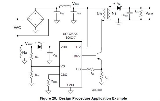
So I attempt  to work out the full design procedure. Everything fine until I get to the transformer (coupled inductors for flyback) part on page 20.

tR = 2u, fMax = 74 kHz, DMAGCC = 0.425
So DMAX = 0.501


VINMIN = 230V -15% = 230 * 0.85 = 195.5
VBULKMIN = VINMIN * sqrt(2) * 0.8 = 221.2 V, the 0.8 is for 20% ripple on bulk capacitor.
VOCV = 5V
VF = 310 mV
VOCBC = 0, I don't use this

Nps(max) = 49.1, that is pretty large

I was thinking about this one from Pulse Electronics

So my Nps = 17.2

Rather than continuing with the selection of RCS value I realized I already also defined the primary inductance with the selection of this transformer.
Lp = 544 uH

This is a significant lower inductance compared to to one I get with the equations.
I use the equation below to calculate the peak primary current.

= 0.9, they said it was a good approximation
IPP(max) = 242 mA
So for my very small output power it is fine to use a lower inductance on the primary and allow the peak current to be higher, is it?

VCST(max) = 735 mV
RCS = 3.0 ohm, standard e24  
I'm not completely certain about the verification of the minimum on time, should the calculated value be higher OR lower than the 300 ns specification? And what do I need to use for VCST(min) the min, typ or max specification? And VCST(max)?

For both typical I get:

VIN(max) = 230 + 15% = 230 * 1.15 = 264.5 
tON(min) = 85.7 ns


Also for the next check. Does the calculated value for tDMAG(min) be higher OR lower than the 1.2 us specification? And which tON value do I need to use in the equation.


I hope I can get answers to there questions. So I have a better change it works when i make it.

Best regards,
Maarten


  • Dear people,


    Something when wrong with the equations so I uploaded a PDF document with correct formatting.


    Best regards,

    Maarten

    ucc28720_design.pdf
  • Hi Maarten,

    If I understand you correctly you want to use an already available transformer with a primary inductance of 544uH to provide 1W out at 5V.

    The equation you use is correct. Po = 0.5L*I^2*f

    f is the average switching frequency and you probably need to use 50kHz here because of switching jitter and the effect of input voltage ripple and because the UCC28720 is constrained in its search for the quasi resonant switch point.

    80kHz is the max switching frequency so 50kHz is good average switching frequency value.

    This give a value of IPP = 286mA with the above equation.

    To guarantee you reach this peak current value you need to use the min value of VCST(MAX) = 0.735

    So RCS = 2.5 Ohms. You can leave space for 2 parallel parts to adjust this value.

    The value of TDmag is set by the magnetising inductance ringing with the transformer primary capacitance. Its value will be seen when you build the circuit. You can see a change in its value when you adjust the snubber diode and make changes to the switching transistor. But its value is not critical to the design of the transformer.

    Regards,

    John

  • Dear John and the rest of the readers,

    I really hope you can find some time to help me further on the issue. Attached is my message in PDF.

    Regards Maarten

    ucc28720_design_follow_up.pdf
  • Dear TI people,

    I'm still stuck on this issue. I'm thinking about an approach to increase my changes to get some help on this. So how about this one:

    As the UCC28720 is a device designed for minimal no load consumption, Low cost, minimal BOM count and small size. I think my application of just 1W might be a good candidate for a sort of reference design.

    If I promise to share my final schematic together with an Excel sheet that calculates all the parameters on this forum. Would you be willing to help me getting there?

    I also think the snubber circuit should be considered a necessity addition to the schematic shown in the design procedure. Based on John's message.

    So I really hope to hear from TI about this!

    Best regards,

    Maarten