This thread has been locked.

If you have a related question, please click the "Ask a related question" button in the top right corner. The newly created question will be automatically linked to this question.

LM25011-Q1 Regulator failing and not regulating

Hi,

We're experiencing some issues with the LM25011Q1MY/NOPB part, a switching regulator. The most typical failure mode is that there is no regulation, i.e. that both the output voltage and current are not regulated.  There is some dropout, but otherwise the output voltage essentially tracks the input voltage.  This device is being used to charge a 4-cell Lithium battery, so we are concerned about excessive current, and especially over-voltage conditions. Another failure that was seen recently is the chip presents a short to the input supply voltage.

After some troubleshooting, we determined that, after the part stops regulating, the Feedback Voltage (out of pin 6) is ~3.35V (instead of 2.51V) and the chip is not switching on pin 9 (constant on). This was with an input voltage of 24V and designed to regulate 16.6V out. 

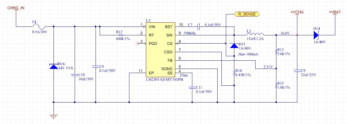
I've attached the schematic of the control circuit we're using with the chip. Any insight into why the chip would keep failing like this? 

Thanks

  • Hi Shubham,

    You cannot charge a lithium ion battery, or any battery,  with a voltage source only. You need to charge a battery with a current source. That means that when the battery is below its Open Circuit voltage you have supply it with a constant or regulated current, usually equal to 1 C. Once the battery reaches its oc voltage, you need to switch to voltage source mode and top off the battery until the current level drops to 01C. C is the charge capacity of the battery and is listed on its data sheet.

    The battery is a low impedance voltage source. That is  why you are seeing high currents. You are basically placing a short on the output of the converter. You cannot charge a battery with another low impedance voltage source. You must use a high impedance current source until the battery voltage reaches its open circuit voltage. 

    Send me the details and I can provide a design.

    Hope this helps,

    Chuck

  • Hi Chuck,

    I should've mentioned this earlier but we're using this circuit as part of a larger board in order to charge the batteries. So the board does indeed charge batteries as expected (under normal operation), however when it fails, it is at this voltage regulator chip. 

    Shubham

  • Hi Chuck, thanks for your reply.  I'm working with Shubham on this. 

    The device provides current limiting, so under normal operation, it is a constant-voltage / constant-current regulator.  During the initial charge the current is limited to about 0.3C, and when the voltage reaches about 4.1-4.2V/cell, it automatically switches to constant-voltage mode.

  • Hello AQ,

    Okay, that makes sense. Clever idea actually. Did you check to see if  you have the required ripple voltage on the CS pin? The data sheet says you need 25 mVpp and if you are running at a higher frequency you may need higher ripple. If the ripple voltage goes too small when you transition from constant current to constant voltage and normal operation you may lose control and start a small signal oscillation. This noise gets into the error amp and causes the converter to lose regulation.

    Another thing to check would be the sense resistor. If you get it too hot during constant current mode it could be at too high a resistance when you go to constant voltage mode.

    Hope this helps,

    Chuck