


Hi,
I am reading the application report SLVA345B "Supplying TPS61200 With a Single Solar Cell" and I have some questions.
In my device I need to boost the voltage of the solar cell up to 5v. Acording with datasheet I have to choose proper values for R1 and R2 in this diagram
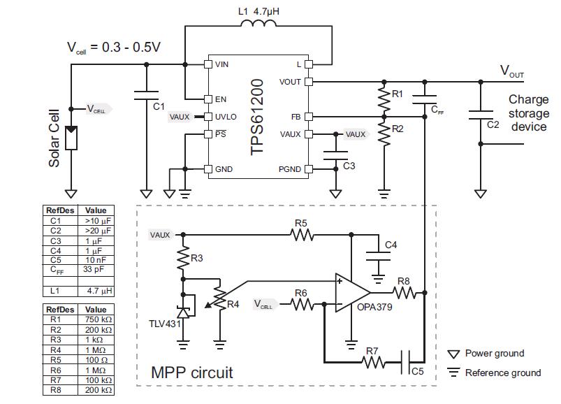
The question is, do I have to change any other componet's value? I don't think so, but I would like to be sure.
Next thing is in the MPP circuit. If I understand its function properly it compares Vcell with a voltage selected by changing R4 resistance, in order to avoid Vcell getting higher than a selectable value. My question is: Can I just choose a fixed value with a voltage divider or a voltage reference? For a single solar cell I believe its voltage should not exceed 0.4V otherwise it would not be able to supply current.
Thank you.

