Hello there,
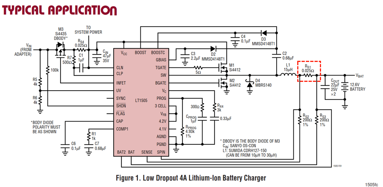
I would like to build a mobile USB charger. The device would consist a 6 li-ion cells connected in 2 pararel series (2 x 3), giving 12.6 V. I intend to use this IC for charging the li-ion pack: LT1505
As most of the charing IC's it is using sensing resistor that is placed between the possitive charging output and the possitive terminal of the battery:
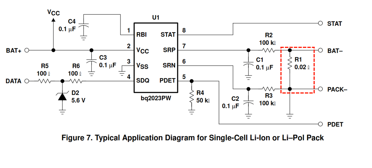
Now in addition to this IC i would like to use a general purpose microcontroller for driving everything and an coulumb counter BQ2023
This IC on the other hard places sensing resistor BELLOW the battery pack:
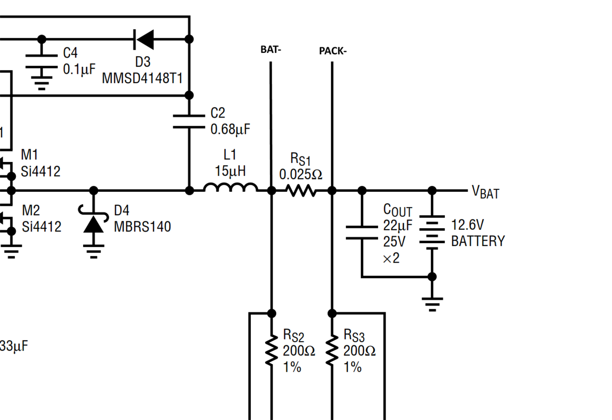
This would give me a total amount of 2 resistors in series with the battery pack, one for coulumb counter and one for the charger. This would lower the voltage drop on the batteries which will to fast charging termination. I was wondering either it is possible to use the exact same resistor (the one from LTC4150 schematic) both for the charging and chargees counting purposes for both IC's. Can BQ2023 have a resistor placed "uppon" battery pack instead of "under" it?
I would aprichiate any help


