This thread has been locked.

If you have a related question, please click the "Ask a related question" button in the top right corner. The newly created question will be automatically linked to this question.

Boost cap between VBST and SW voltage rating

Other Parts Discussed in Thread: TPS62200, TPS562200

What voltage could be seen across the boost cap?

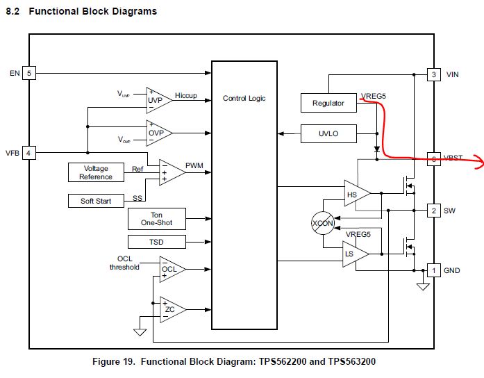
Assuming Vin is 12V, the wavefrom on the SW pin is 0 to 12V switching waveform. The VBST pin presumably has a voltage already on it, so that during the high cycle of SW, the VBST voltage can be pushed up for a source to bias the N-ch FETs. But how much?

If we're to allow for DC derating of ceramic caps, then the maximum voltage imposed across the cap is needed, so a cap of a suitable voltage rating and derating spec can be used.

The minimum required capacitance of the cap would also be useful. I didn't spot either of these in the datasheet (TPS62200).

Regards,
Lyndon

  • Hi Lyndon

    I think you are referring to TPS562200 (not TPS62200).

    The bootstrap cap CBST is connected to the internal 5V regulator of the TPS562200 (VREG5) vias a diode.  So when the LS FET is on, the switch node is pulled low the cap CBST is charged to ~5V.   See below: 

    The voltage across CBST is ~5V so a 10V rated cap will be fine.  When the HS FET is turned on, the SW node goes to VIN.  The voltage across CBST stays at ~5V and the VBST pin is clamped to VIN + 5V.  The abs max rating for VBST is 6.5V above VIN which is the ~5V of  VREG5 plus some margin.

    The minimum value isn't specified but a 100nF ceramic capacitor should be used.


    Does this answer your question?


    REgards


    Jim

  • Thanks Jim, that'll do nicely.
    Cheers
    Lyndon
  • Jim,

    We accidentally used 22pf caps for the boost cap on some boards that went out in the field.  They are working but the TPS562200 is getting VERY hot.  The  IP voltage is 12V.  Output voltage is 3.3V at around 250ma.  We are getting these boards back to correct the boost cap error.  Is this causing the part to run hot?

  • Yes I do think it is likely that the 22pF bootstrap cap is causing the device to run hot. Usually this cap is ~1nF. Its job is to make sure the high side fet is fully turned on. At 22pF I suspect the HS fet is not turned on fully and is runnning in its linear region hence burning a lot of power and getting hot.
    Jim
  • Correction, the recommended Cbst is 100nF!Jim