This thread has been locked.

If you have a related question, please click the "Ask a related question" button in the top right corner. The newly created question will be automatically linked to this question.

Noise on TPS799 LDO output with EN low

Other Parts Discussed in Thread: TPS63000, TPS799XXEVM-105, TPS799

We have a design that using a TPS63000 - Buck-Boost Converter providing power to the TPS79928 LDO.  

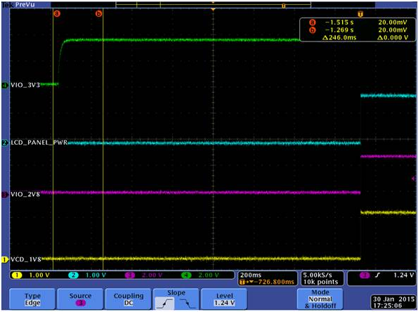
We are seeing an unexplained pulse out (VIO_2V8) of the TPS79928 LDO when the enable signal (seen below as LCD_PANEL_PWR) is low the whole time from power-on-reset.

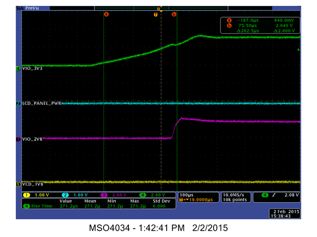
Currently this issues seem related to the rise time for the TPS7992 input but we don’t see any rise time requirements in the TPS79928 specifications.

We have connected the TPS63000 in our system to the TPS799xxEVM-105 and see the same noise in Figure 1 below.

Figure 1 below shows the unexplained pulse and figure 2 shows the pulse gone after adding a soft start circuit to TPS63000 thus slowing down the rise time to the TPS79928 input.

TPS79928 (IN) - VIO_3V3 (GREEN)
TPS79928 (EN) - LCD_PANEL_PWR (BLUE)
TPS79928 (OUT) - VIO_2V8 (PINK)

Figure 1: Pulse on output seen with Enable (LCD_PANEL_PWR) Low.

Figure 2: Soft start circuit added to TPS63000 to slow down the rise time to the TPS79928 Input


  • Hi Brad,

    Could you please share what channel one is?

    Very respectfully,

    Ryan

  • Ryan,

    Sure. channel 1 is the output of a transistor network where the VLCD_2V8 output drives the base of a NPN transistor. Once a high is seen on the VLCD_2V8 domain it turns on the NPN thus turning on a PCH MOS FET transistor. Once on the PCH-transistor provides voltage to the VLCD_1V8 domain.

    Has TI seen a case where a similar pulse appears on the output of a TPS799 LDO when the enable signal is low at power up? It seems we are able to eliminate the unwanted pulse by slowing down the rise time of the supply used to power the TSP79928 LDO. We have not yet tested the slower rise time across temperature.

    Thanks,
    Brad
  • Hi Brad,

    Thanks for the explanation on VCD_1V8. Based on your two scope shots, I wanted to make sure that it was not the cause of the pulse. It sounds like it is the result of the pulse.

    Could you take an additional scope shot that you zoom in on the pulse duration? Since it looks like modifying the input signal helped, I am particularly curious about the ramp rate and what level Vin was at when the output pulsed.

    Very Respectfully,
    Ryan
  • Ryan,

    Correct.  VCD_1V8 appears to be a result of the pulse.

    Here is the additional scope shot when the pulse is seen out at VIO_2V8.

    Regards,

    Brad

  • Hi Brad,

    Thanks for the confirmation and additional scope shot. I also appreciate the added cursors!

    I was able to reproduce this here on an EVM. It looks like the pulse occurs right about when the input hits UVLO. A couple of ways to help minimize this is to increase the output capacitor, increase the load or (as you found) slow the ramp rate.

    Very Respectfully,
    Ryan