This thread has been locked.

If you have a related question, please click the "Ask a related question" button in the top right corner. The newly created question will be automatically linked to this question.

Aged battery detection using bq27510-g1

Other Parts Discussed in Thread: BQ27510, BQ27510-G1, BQ27505-J4

Hi,

My application requires prevention of using aged/degraded battery pack (or battery pack with same chemistry but lower capacity). The purpose is to ensure there is enough battery capacity to sustain for whole operation whenever a battery pack is inserted to my system.

Example, my system suppose to use battery pack with 2200 mAh capacity (2 parallel cells pack). I have a golden profile of 2200mAh programmed into bq27510. So subsequently in my application is it possible for bq27510 to do a detection whenever a degraded battery pack (eg. capacity degraded to 1760) is inserted and this information is updated to my system? Or certain learning cycle has to be made for this to happen? If yes, what are the conditions to enable updating of the degraded capacity information to happen?

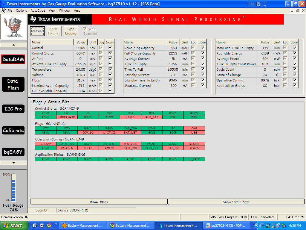
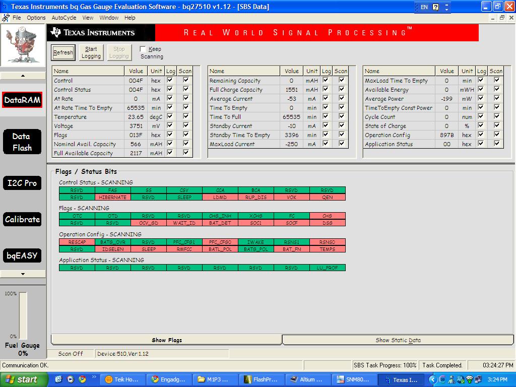
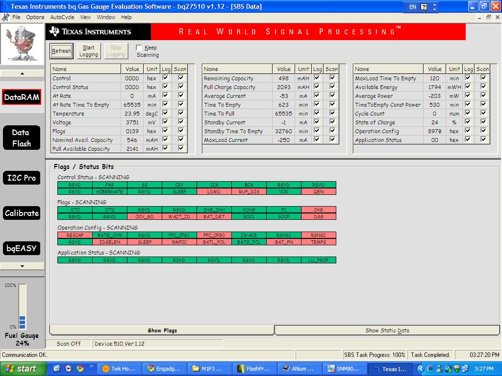
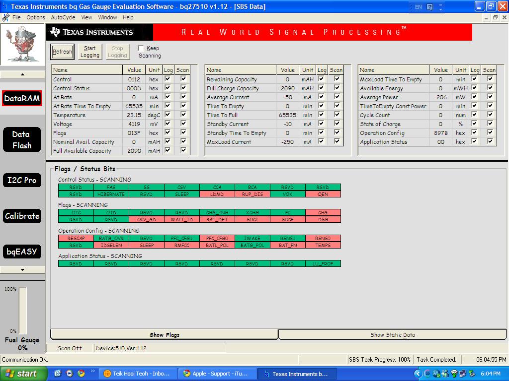
I have tried using battery pack with reduced battery cell to single cell (1100 mAh). It seems that bq27510 was unable to reflect the reduction of capacity. It still shows the full charge capacity to be about 2200 mAh. 

Please help. Thanks.

Teoh

  • Teoh,


    bq27510 will not know the battery capacity initially. However, after two relaxation periods with discharge more than 37% of design capacity in between, the gauge will update the Qmax, which should be the aged battery max chemical capacity.


    Thanks

    Ming

  • Using the bq27510-G1, the only way the gauge will learn the new capacity of the pack you insert is as Ming says.  I’d like to add to his information with a discussion about battery aging and which parameter you should monitor.

    There are two things that happen when a pack ages:

    1. the capacity (Qmax) decreases.  We typically expect 3-5% reduction in capacity after 100 cycles for traditional Li-ion cells.
    2. the internal impedance (Ra tables) increase.  We typically expect impedance to nearly DOUBLE after 100 cycles for traditional Li-ion cells.

    You can see that the Qmax reduction is not such a big deal (2200mAh -> 2090mAh), but the resistance doubling will have a significant impact on your usable capacity.  Twice as much energy will be lost to the battery’s internal impedance, significantly reducing your run-time and usable capacity.

    As Ming said, it will take at least 37% of a discharge or charge with sufficient relaxation times before and after to update Qmax.  However, Ra (impedance) will be updated much sooner during a discharge.  Therefore you should see a change of FullChargeCapacity() much sooner than you would see Qmax updated in dataflash.

    Our newer firmware versions have a function called StateOfHealth() which will tell you the ratio of usable capacity (FullChargeCapacity) to DesignCapacity() in percentage terms.  
    You can read more about this function in either of these datasheets.
    Pack-side gauge:
    http://focus.ti.com/lit/ds/symlink/bq27541-v200.pdf
    Host-side gauge:
    http://focus.ti.com/lit/ds/symlink/bq27505-j4.pdf

    If you can change your design to a bq27505-J4, you can use this function.
    Alternatively, you might consider implementing something similar in your host program.
    Basically I am saying that you should look at the reduction in FullChargeCapacity() over time, not Qmax.

    Regards,
    David

  • Hi David,

    Thanks for the suggestion.

    Regarding the updating of FCC after insertion, how soon would it be updating? I was doing a test using a 2200 mAh battery pack with additional resistance (5 ohms) added in series to simulate increased impedance of aged battery pack. Just to see if there will be any changes in the FCC. So far, FCC remains to be near 2200 mAh. Most likely I will need to continue to go through the process of discharge it to >37% and have the pack to relax for 5 hours. Or is there any problem with this setup? By the way, do we need to start off by inserting a relaxed battery pack for this test situation for accurate OCV reading?

    Regarding the OCV reading, I also observed that the time to BAT_GD is a bit long at 4.4s. Is this normal?

    Regards,

    Teoh

  • First, 5 ohms is probably too high and not realistic except for an extremely old.  A typical cell of your capacity (2200mAh) might be in the ballpark of 500milli-ohms of internal impedance when new, and perhaps up to 1 ohm after 100 cycles.  However, cell impedance also increases at low state of charge, so the ball park I am talking about is for maybe 5-10% charge or higher.

    If your system is just powering up when you insert the battery, I would expect the gauge to take 2.4s to initialize and report an OCV reading.  There might be something else going on to make the BAT_GD pin take 4.4s, but I can't think of it right now.

    Yes, you do want to insert a relaxed battery pack to ensure you get an accurate OCV measurement.

    When you insert the battery and see FCC remain at 2200mAh, have you applied any load yet?  Although you've put that huge series resistance in there and would expect FCC to be reduced due to the higher impedance, the gauge will not detect that higher impedance unless you have a load and therefore see an IR drop.  Applying a load will allow the gauge to immediately get a fix on the impedance (at that SOC), and it will scale the entire impedance table, but there are some filters and limits in the algorithm to keep it from jumping to a very big value quickly as a real battery wouldn't have large jumps in impedance over a short period of time.  As you realize, you will need to do the 37% charge or discharge with a relaxation to have the Qmax updated, which will then change FCC.  However, just putting a 5 ohm resistor in series to simulate an aged cell does not reduce the capacity of your battery, so you are only simulating one aspect of an aged battery.

  • The system is already up and running when the FCC remains at 2200mAh. Anyway, as you have pointed out the resistance might be too large to simulate the realistic change in battery internal impedance. So I have tried with 500mohm instead and the FCC still remains unchanged. Same when using the 1100mAh battery pack.

    I have tried under these 2 scenarios below, for each of  the scenario,  the device is being programmed with the golden profile so that the default and the 2 dynamic profiles are reset:

    1. insert relaxed battery (1100mAh or simulate with 500mOhm resistor) --> discharge to >37% delta of SOC --> shutdown system (current consumption <1mA) and let battery relaxed for 5 hours --> power on system to read the FCC

    2. insert relaxed battery (1100mAh or simulate with 500mOhm resistor) --> charge to >37% delta of SOC --> shutdown system (current <1mA) and let battery relaxed for 2 hours --> power on system to read FCC

    Just to further clarify: FCC will only be updated after Qmax is updated? There is some confusions here as you have mentioned in one of your previous reply that the FCC should be updated when the Ra table is being updated, way sooner before the Qmax is being updated. I was trying to verify on this but it seems I am still unable to see the change.

    Will try to do a continuos charge-relax-discharge-relax cycle to see if this helps.

    I have also observed that the RUP_DIS bit is set to '1' during the process. Is this the main reason that I do not see the change in FCC? But I could not seem to clear it away. Here is the screen capture of the flags settings (for the case of 1100mAh battery):

    Just wondering, is this FCC updating similar to the battery analyser that able to identify the battery status when it is inserted? The battery analyser can show the status quite fast, no matter what capacity of the battery is inserted. 

    Regards.

  • Teik, 


    The IT is not enabled. Please send commend 0x21 to enable IT so that both VOK and QEN is set (red) and re-run the cycle.


    Thanks

    Ming

  • Hi,

    Thanks for the suggestion. Here are the steps to the results:

    1. Insert fully relaxed battery (single cell, 1100mAh) while system off (<1mA consumption).

    2. bq27510-g1 on my system are programmed with golden profile for 2200mAh battery (two 1100mAh cells in parallel)

    2. Turn on system 5 seconds after battery insertion (to enable good OCV reading as time to BAT_GD found to be 4.4s).

    3. Enable IT by sending sub-command 0x0021 by using I2C Pro that comes with the EVSW.

    4. Charge battery. I have the charging log file if you need to check.

    5. Initial reading of the battery at beginning of charging:

    Voltage: 3.964V Nominal avail. capacity: 374mAh Full avail capacity: 2141mAh Remaininf capacity: 327mAh FCC: 2094mAh SOC: 16%

    Control status: 004B 

    6. Observed that the battery is charged up to Remaining capacity=1247mAh @ SOC=60% with FCC remains unchanged at 2094mAh. Then upon full charged detected (Flags change from 138 to 238), the RC and SOC becomes 2094mAh and 100% respectively.

    7. Shutdown system to relax the battery for 2 hours.

    8. Power on the system and check the battery status. Please see the screen capture below. The RC and SOC change to 0. Looks strange.:

    9. Re-enable IT again using I2C Pro. The RC changes to 2037 and FCC changes to 2093. SOC is 98%.

    10. Discharge the battery to >37% and shut down the system to relax the battery for 5 hours.

    11. Power up the system to check the battery status. The screen capture as below. Again, as observed in charging stage, the RC and SOC are set to 0. But the FCC did have a substantial change to 1551mAh (although it seems to be a bit far off from the 1100mAh).

    12. Then I tried to remove the battery and re-insert the battery. The screen capture as below. The FCC changes back to 2093mAh. In this case, the dynamic profile of the two most recent battery pack were not stored? 

    Please help to advice if there are any problem with the procedures.

    The results seems to show that FCC is not able to update so soon. And the main problem is that it cannot recognise the profile of most recent battery used.

    According to application note slua544, the IT suppose to be cleared in the generated golden image for mass production use. So in this case, would the fuel gauge still be able to recognise the new battery profile and update the FCC and Qmax? It seems to be contradicting. 

  • Hi,

    Just to repost the broken screen capture image for steps 8:

  • Teik,


    Can you send me the log file as well as gg dump?


    Thanks

    Ming

  • Can you please explain your setup?

    Here is my understanding of your system:

    bq27510-G1 is on your system board and communicating with your main host by I2C.

    You also have I2C test points so you can communicate with the gauge using EV2300/EVSW.

    How do you discharge the battery? 

    Your screenshots show a system load of about -50mA.  This is about a C/44 rate.  It is not a significant load on your battery if the capacity is really 2200mAh.  There will be very little IR drop for such a load.

    Do you have a higher power/current mode in your system?


    Now I will try to answer your last question about the IT Enable bit and production:

    Your golden file should not have IT Enable set (in data flash).  You will program your bq27510-G1 with the golden file in production, do any system testing, then send the IT_ENABLE command as the last step.  This will change IT Enable in dataflash to =1.  From then on IT Enable should be set for the life of your product.  Batteries will be inserted and removed, the system will turn off and on, but IT Enable will always be set and the gauge will be watching for batteries to gauge.

    The reason you don't want to have IT Enable set during your production is that you might have test currents and voltages applied.  You don't want the gauge to be confused and try to gauge and learn a power supply instead of a real battery.  So you leave IT Enable cleared until you are ready to ship the system and you know there will be no voltage on the PACK pins or current through the sense resistor unless it is a real battery.