This thread has been locked.

If you have a related question, please click the "Ask a related question" button in the top right corner. The newly created question will be automatically linked to this question.

LMR16006 Thermal Shutdown

Other Parts Discussed in Thread: LMR16006YEVM, LM46001, LMR16006, LMR16006XEVM

Hi

We have evaluated LMR16006YEVM at the following condition. However the device repeats start and stop because of thermal shutdown.

(Condition : Vin=48V, Vout=31V, Io=0.6A. Fsw=2.1MHz

 Modified : resistor of voltage divider , Inductor : 47uH(DCR=150mohm), Diode (VM=0.85V) )

We have some question for this phenomenon.

1. Is it possible to operate at these condition?

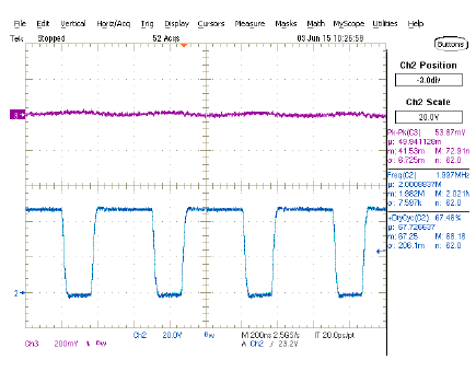
2. We obtained the switching waveform before shutdown.  The rise and fall time of switching looks gently

    This means the switching loss is increased. How much is the Qg and TR/TF of integrated MOSFET?  


Our customer is going to use this device at the above condition.

Please let me know if you have any question.

Regards,

Koji Hamamoto

  • Hello,
    48Vin to 31Vout at full load and 2.1MHz is indeed quite demanding of this device. Switching losses at 48Vin will be quite high at higher frequency and the additional internal LDO loss would be high at higher input voltage. I would suggest dropping the switching frequency to the 700kHz option.

    Layout would be key too. Since there is no exposed pad to release heat in to the board, the SW node would need to be able to do so. making the SW node fat and wide can help a bit. If you share your layout, we could give you some feedback on it.


    Regards,Akshay

  • Hi Akshay-san

    Thank you for your quick reply.

    I understand the losses which is switching loss and LDO loss are large at high frequency and high vin.

    We will suggest to the customer about setting at low frequency. However I have two question.

    1. I have tried to simulate by WEBENCH at that condition. (Vin=48V, Vo=31V, Io=0.6A, Fsw=2.1MHz)

        I understand it depends on laytout.  However the result is looks good. Why is that different from actual result? 

       http://webench.ti.com/appinfo/webench/scripts/SDP.cgi?ID=95F637CCF5449A07

    2. For your question which is about layout. The board we had evaluated is TI's EVM (LMR16006YEVM)

        We have modified the EVM for our condition.  Then we evaluated but it did not work well. (thermal shutdown works)

        Do you have any other idea for this issue?  ( frequency and layout and ....)

    Regards,

    Koji Hamamoto

  • Hello,

    Lowering the frequency is the only option with this device because there are no other controls on it. Since the input voltage and output voltage of the design are quite high, I would actually suggest use of the LM46001. The LM46001 has RT pin that can be used to lower the switching frequency to all the way down to 200kHz. And it also has an exposed pad that connects to the ground on the board and will help sink heat in to the board.

    As far as Webench goes, I am not sure why the results are optimistic. I will forward that question to the engineers in the Webench department and try to get a response.

    Regards,
    Akshay

  • Hi Hamamoto-san,

    Just to clarify, your question is about why the trise/tfall times in the electrical simulation model are different than the amount seen in the bench data?

  • K.Hamamoto- san,

    We don't model the thermal behavior ( or thermal shutdown) in WEBENCH PSpice model, so if the part is shutting down on the bench due to temperature rise, it will not show up in WEBENCH.

    Thanks,

    Ajit

  • Ajit, Kevin,
    I am assuming they are looking at the operating point values. The power dissipation in the IC is calculated around .45W and the IC Tj is about 77degC. Hence he is wondering whether that is correct or not. On the bench his device is going in to thermal shutdown which means that the IC Tj is well over 125C.

    Regards,
    Akshay
  • I am going to close this thread here. I have split it and sent the questions from Koji Hamamoto to the Power and Lighting Tools forum because the questions are about Power Webench. Please follow up over there. Thanks!

    Regards,
    Akshay
  • Hi Akshay-san

    Thank you for your support.

    As you commented this thread was closed.Then you passed this issue to another team because this issue is about Tool issue.

    However I need some feedback about this issue. What should I do next?

    Regards,

    Koji Hamamoto

  • As Akshay suggested, have you tried to reduce the switching frequency? You can send us the schematic and layout for review.

    Since the package of LMR16006 is very small and no exposed pad, the Theta JA on the datasheet shows 102C/W. That means 1 W of power dissipation will generate 102C of temperature rise. The output power of your design is 31V*0.6A = 18.6W. It is pretty large for such a small packaged part. Is your customer willing to consider a part that's larger in size but has much better thermal performance? Please take a look at LM46001. It is a synchronous regulator IC with Theta JA = 39.9C/W. For Vout = 31V, it is OK as long as Bias pin is tied to ground.

    -Yang

  • Hi Yang-san

    Thank you for your support.

    >As Akshay suggested, have you tried to reduce the switching frequency? You can send us the schematic and layout for review.

    Not yet. We are trying to get the EVM of X version (LMR16006XEVM). You can refer LMR16006YEVM for the schematic and layout.
    Because the evaluation board is LMR16006YEVM what we have evaluated.

    On the other hand, we measured the waveform of SW node. It was different from the result of WEBENCH.
    The result of WEBENCH looks good.
    webench.ti.com/.../SDP.cgi

    I am considered the switching loss is larger than simulation. Because the rise time and fall time of SW node is slower than simulation.
    Why the difference? This is my next question. (Our customer ask same question)

    Regards,
    Koji Hamamoto
  • Hi

    How about this?

    The detail of schematic is following ;
    They uses LMR16006YEVM.
    modified Vout setting. --> from Vo=5V(R3,R4) to Vo=31V
    modified the inductor --> from 25uH(L1) to 47uH
    modified the diode --> from MBR1H100SFT3G to EC21QS10-TE12L(Vf=0.85V)

    LM46001 what you recommended is good. However the cost requirement is very tough and they wants small size package solution.
    That why we selected LMR16006.

    Please let me know if you have any question.

    Regards,
    Koji Hamamoto