This thread has been locked.

If you have a related question, please click the "Ask a related question" button in the top right corner. The newly created question will be automatically linked to this question.

LMZ22008 inverting application

Other Parts Discussed in Thread: LMZ22008

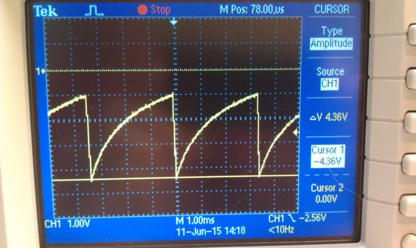
I'm looking to generate -4.25V from +12V using the LMZ22008 simple switcher and having trouble getting it to run.  During debug, I have a very light load (100mA) and I'm getting my Vout to look like...

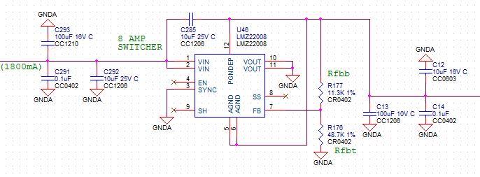
I followed your AN2027 EXCEPT that it does not mention what to do with the SYNC input.  I want the unit always enabled, so I left EN open.  If I want it to control SYNC internally (no external SYNC applied), what do I do with this input?

For example...+12V on left, -4.25V on right.

Thanks for your help.  Tom.

  • Hi Tom,

    From your schematic, the SYNC pin connection could be the issue. When not in use, SYNC should be tied to the lowest potential of the IC, which is AGND pin. Please tie SYNC to the same net as AGND. The 'GNDA' net in your schematic is actually 4.25V higher than the AGND pin.

    The EN, SH and SS pins can be floating when not in use.

    The Cin and Cout in your design seem too less. Cout you might need ~330uF, Cin may be 2*10uF. How much is the nominal load current for this design?

    Regards,

    Yang

  • Yang,
    Thanks for your inputs. Yes, this did it. It now reads a steady voltage.

    What is the minimal current load I need to safely startup in this circuit?

    Also, I'd love your advice for Cin/Cout. My circuit should draw 4.1 amps. As you can see in the schematic, my Cin is 100uF || 10uF || .1uF and my Cout to ground is the same. I also have a Vin to Vout coupling of 10uF. Any recommendations would be appreciated. If you could describe what improvement I would see by making the capacitor changes, I'd learn for the future.

    Thanks again,

    Tom