This thread has been locked.

If you have a related question, please click the "Ask a related question" button in the top right corner. The newly created question will be automatically linked to this question.

LM3668-Q1 Maximum Load current for Vin=3V to 3.3V

Other Parts Discussed in Thread: LM3668

Hello,


Customer wants to use LM3668-Q1 with following condition and needs to confirm if they can use LM3668-Q1 or not.


Vin: 3.3V

Load current: 660mA max

Ta: 105C max


First page of datasheet has following feature.

– 700-mA Maximum Load Current for V IN = 3 V to 3.3 V 

Please advise the Ambient Temperature range for this feature.

Customer needs above answer to decide if they can use LM3668-Q1 or not, and they needs to decide tomorrow.

So please answer above question, and Junction Temperature margin when Ta max is supposed to 105C and 85C, as soon as possible.


Best Regards.

  • Hi,In order to estimate Ta-max, there is an equation in datasheet.
    TA-MAX = TJ-MAX-OP – (RθJA × PD-MAX)
    TJ-MAX-OP = 125, RθJA = 37, PD-MAX = 5*0.66*(1-0.75) = 0.825(assuming 75% efficiency based on efficiency curve in datasheet, 3V in, 5V out, 0.66A)
    Then, Ta-max = 125 - 37*0.825 = 94.47C, so max ambient temp for this Vin and load condition will be 94.47C. Unfortunately, this device can't support 105C at this condition, which is too close to junction temp already.
  • Hello Sung-san,


    Thank you for your answer about Tj calculation.


    Please answer following additional question about “Switch peak current limit, min”.

    Customer wants to confirm margin of “Switch peak current” when Vin=3.3V and Load current= 660mA.

    Datasheet has following “Switch peak current limit, min” specification when VIN=4V.


    Please advise if current limit minimum 1.6A is decrease or increase when VIN=3.3V, and how is amount.


    Best Regards.

  •  Hi,

    If input voltage drops, max SW current will also drop. Max Iload was set based on measured value from the validation and sim result.

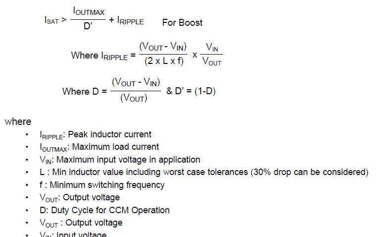
    There is a equation on datasheet to calculate Isat(inductor current) also shown above.

    The calculated Isat for Vin=4V, Vout=5V, Iout=1A condition is 1.341A. Iswmax should be bigger than this. 1.6A is ~20% bigger value than Isat value.

    In same way, Isat for Vin=3.3V, Vout=5V, Iout=0.7A condition is 1.188A, then adding 20% of this, Iswmax will be ~1.42A or little less.

    Sorry, there is no measurement data for all voltage/load conditions available.

    Hope this helps.


  • Hello Sung-san,

    Thank you for your answer.

    Could you please give me measured and simulation data that you decide following maximum load specification.


      Vin=3.3V, Vout=5V, Iout=0.7A


    Best Regards.

  • Hi Ushikubo-san,


    This is my test result.

        Max Load(mA) - No Thermal shutdown/Over current limit/Higher than 4.5V
          25C -40C 125C*
    Output option Input voltage(V) load current(mA) Output voltage(V) Output voltage(V) Output voltage(V)
    5.0V 2.7 0 4.998 4.978 5.008
    2.7 100 4.997 4.976 5.006
    2.7 200 4.992 4.949 5.002
    2.7 300 4.989 4.925 4.997
    2.7 400 4.989 4.946 4.985
    2.7 500 4.986 4.956 4.95
    2.7 600 4.984 4.946 4.89
    3.6 0 5.001 4.979 5.001
    3.6 100 4.997 4.971 5.001
    3.6 200 4.993 4.961 5
    3.6 300 4.985 4.947 4.996
    3.6 400 4.984 4.932 4.993
    3.6 500 4.981 4.925 4.989
    3.6 600 4.98 4.926 4.985
    3.6 700 4.977 4.929 4.977
    3.6 800 4.976 4.932 4.964
    4.5 0 4.998 4.973 5
    4.5 100 4.995 4.966 5
    4.5 200 4.99 4.96 4.998
    4.5 300 4.989 4.953 4.995
    4.5 400 4.985 4.938 4.992
    4.5 500 4.982 4.927 4.989
    4.5 600 4.978 4.917 4.986
    4.5 700 4.976 4.913 4.981
    4.5 800 4.972 4.912 4.977
    4.5 900 4.97 4.912 4.972
    4.5 1000 4.969 4.911 4.967
    5.5 0 4.994 4.967 5
    5.5 100 4.997 4.968 5.002
    5.5 200 4.994 4.963 5.001
    5.5 300 4.99 4.962 5.001
    5.5 400 4.987 4.957 4.999
    5.5 500 4.984 4.951 4.997
    5.5 600 4.982 4.946 4.995
    5.5 700 4.98 4.943 4.993
    5.5 800 4.978 4.938 4.988
    5.5 900 4.976 4.934 4.986
    5.5 1000 4.979 4.935 4.988

    But the efficiency graph on datasheet also showing max load conidtions are based on the original LM3668(same die, smaller package) measurement result which I don't have.

    Above result was measured on our EVB, so the number may vary a little bit by board layout for heat dissipation, and power loss.

    I'm checking with original designer of this device for sim result for max load support and will update you later when I get it.

    Thanks,

  • Hello Sung-san,

    Thank you for your test result.


    Your results are at Vin=2.7V and 3.6V so it is difficult to judge if LM3688-Q1 can supply 5V/660mA marginally when Vin=3.3V while over operating temperature.


    Could you send me sim result for max load support?


    Best Regards.

  • Hi Ushikubo-san,

    I got the sim result from our design group, but it's only for 3V in, 500mA condition. They don't have 660mA condition.

    I think I can't attach this file on this E2E site. Could you let me know of your email address I can reply back with the attachment?

    Me email address is sungho.yoon@ti.com

    Thanks,


  • Hi Ushikubo-san,
    Forgot one thing. If you are not TI employee, I'm not allowed to send sim result without permission. In that case, it may take some time to get the approval. I hope you would understand the situation.
    Thanks,