Hello,
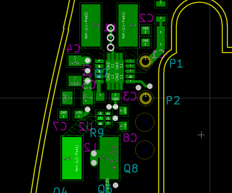
I'm using a 9V into a TPS63061 to give me a 5V rail, then use the 5V rail into a TPS62233 to give me a 3V rail. The 5V rail is used to run a solenoid at high currents for very brief periods (<20ms, with PWM implemented for a portion of that), and the 3V rail is used to power several LEDs as well as an MSP430 and an LCD module. I like the high efficiencies of the TPS62233 because the LEDs are almost constantly on, and actually account for roughly 40% of my power budget. The TPS63061 has similar efficiency benefits, as well as easily allowing the use of pretty much any 9V the user would throw at it (alkaline, NiMH, LiPo, etc.)
When I received my prototype circuit, I noticed that the output from the TPS62233 behaves erratically around 5V - the switching point for the TPS63061 to go from buck mode to boost mode. The output drops from roughly 2.95V to 2.6V (which is outside the operating range for the LCD), and I'm not really sure why. It seems like there's a bunch of noise being introduced. Could there be some kind of feedback/resonance between the two switching regulators? I'm using the same Murata LQH5BPN1R5NT0L 1.5uH inductor for both regulators, and the caps are all the same values used in the EVM modules/recommended layouts. Does the TPS62233 need a chip inductor with more ESR to be more stable?
-
Ask a related question
What is a related question?A related question is a question created from another question. When the related question is created, it will be automatically linked to the original question.


