Hello all,
I am using the TPS61025 in my design.
Under typical conditions, the load on the TPS61025 output is around 15 mA.
However, occasionally, I activate an actuator, and this will bring up the current by about 100 mA temporarily.
I am using the following components:
22 uH inductor: http://www.digikey.com/product-detail/en/CLF6045T-220M-D/445-15128-1-ND/4168212
10 uF input capacitor: http://www.digikey.com/product-detail/en/0/445-7486-1-ND
47 uF output capacitor: http://www.digikey.com/product-detail/en/0/445-11420-1-ND
I am using a single 1.25V NiMH battery to power the system.
I am also using a reset IC such that when the battery falls below a certain threshold, the output of the reset IC drives the enable pin of the TPS61025 low (this is to prevent battery drain). This output goes low when the battery is at 1.0V.
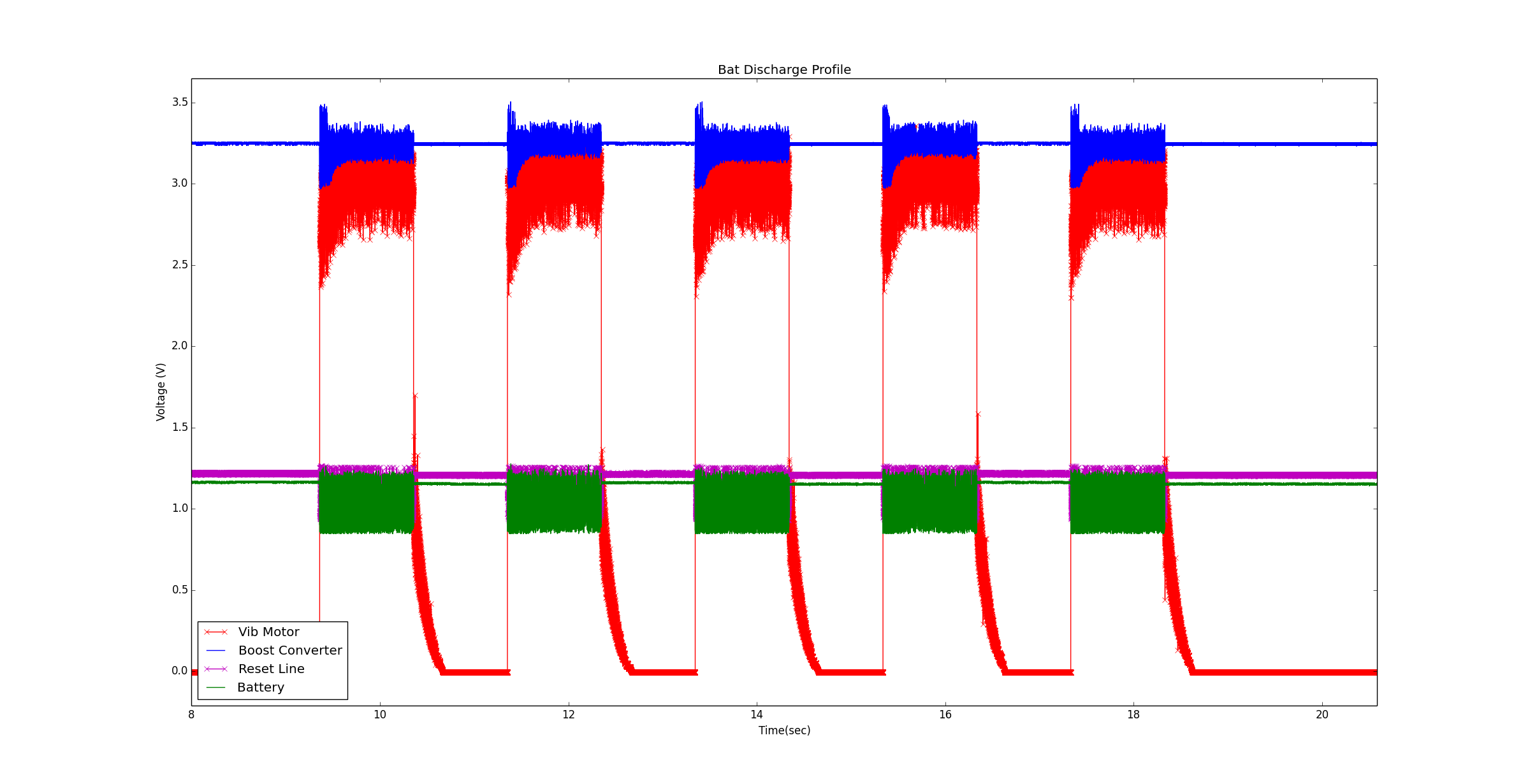
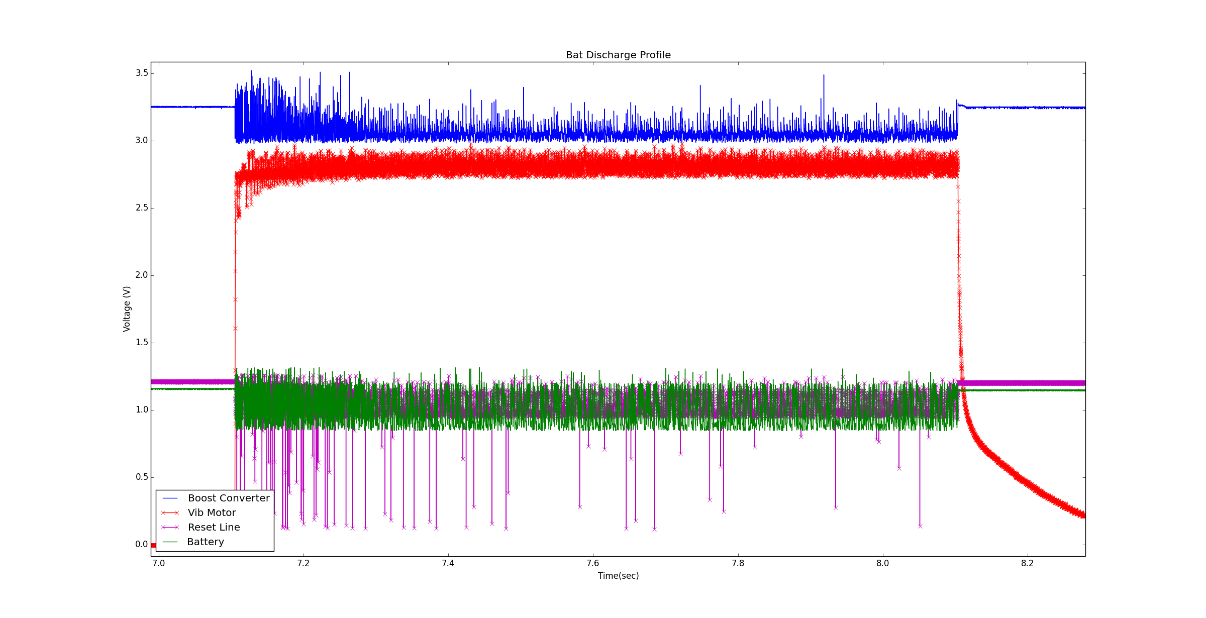
Normally, the system works fine and there are no power issues. However, I activate a vibration motor during before the battery reaches 1.0V (as an alert mechanism), and this causes issues on the power line. Essentially the battery voltage line fluctuates, which causes the reset line to fluctuate.
I have gone through some calculations, and I believed that the component selection should have provided a more stable output. Here are my calculations:
---------------------------------------------------------------------------------------
Iout = 115.0 mA
V_out = 3.3 V
V_bat = 1.1 V
f = 600.0 kHz
IL = I_out * V_out/(V_bat * 0.8)
IL = 431.25 mA
deltaIL = deltaIL = 0.2 * I_L
deltaIL = 86.25 mA
Recommended L = 14.1706924316 uH
deltaV = 10.0 mV
Output Cap Min = (I_out * (V_out - V_bat))/(f * deltaV * V_out)
Output Cap Min = 12.7777777778 uF
---------------------------------------------------------------------------------------
I have attached a plot of the lines.

Thanks,
Mehdi