Hi everyone,
I am doing a project on a digital Power Factor Correction (PFC) Control System Design Based on UCD3138PFCEVM-026. The UCD3138PFCEVM-026 is a standalone boost PFC of single-phase AC input. The EVM UCD3138PFCEVM-026 is used together with its control card, UCD3138CC64EVM-030 to evaluate PFC.
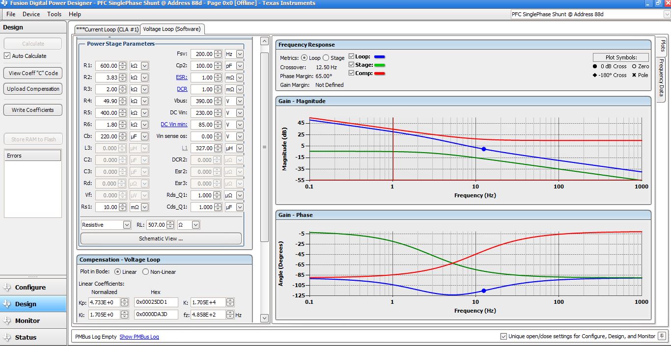
My problem is with controlling the UCD3138CC64EVM-030 board. its control is based on a voltage control loop and a current control loop, where a PI and a PID controller is used for each loop, respectively. I am suppose to calculate the PI and PID parameters based on a desired phase margin and crossover frequency for each loop. I am using the Graphical User Interface (GUI) software to upload these parameters into the control board.
Now, my problem is how can I calculate the parameters of the PI and PID controllers for a desired phase margin and crossover frequency ?
I have tried different methods and the results I am getting are always different than the results shown in the software. is there any documentation that shows how these values are actually calculated in the software?
Thanks in advance
Regards