It happened that during EMC pre-conformance session, we didn’t pass the radiated emission test.
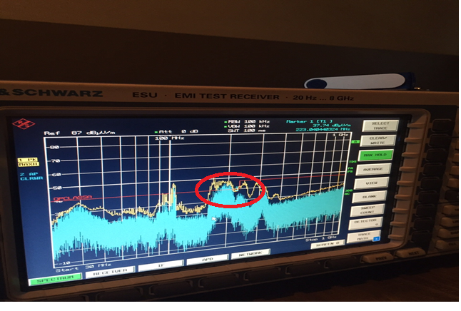
We had some problems with spurious in low frequency range 30/230 MHz IEC 61000-6-3.
In particular we had some spurious around 200 MHz that exceed the limit.
In figure below a picture from EMI test receiver to give you the idea of what we get.
Please consider only the pick around 200 MHz, the others are due to the fact that the picture has been the with anechoic chamber open.
We have been able, with some difficulties and approximation, to reproduce the issues in our lab and at the end we can see a similar behavior also on our spectrum analyzer.
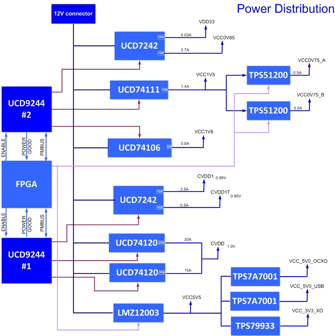
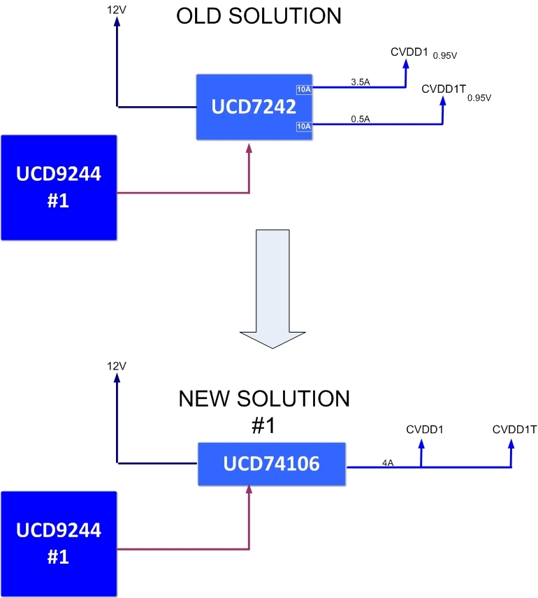
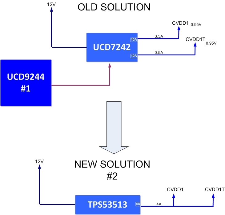
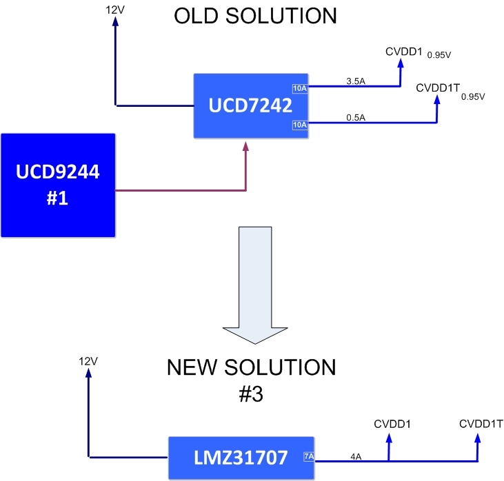
After some weeks of analysis we realized that the cause could be the TI DC/DC converters: UCD74106 (1x), UCD74120 (2x) and UCD7242 (2x).
To demonstrate this we supplied TI TCI6638K2K with external power supplies and the spurious don’t appear.
After this, we switched on the UCD only with a load and the spurious came out again.
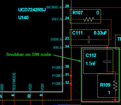
Another thigs that we note is that in UCD datasheet is written “Parasitic inductance in the high-side FET conduction path and the output capacitance (Coss) of the low side FET form a resonant circuit than can produce high frequency ( > 100MHz) ringing on this node.” It seems similar to our case.
What we basically did for AZCOM TCI6638K2K board design is to copy the supply scheme from TI evaluation board EVMK2HX Evaluation Modules from Advantech ( http://www2.advantech.com/Support/TI-EVM/EVMK2HX.aspx ). Also BRD is pretty much the same.
Can you please support us and give us some inputs to proceed in our solving mission?
We would also share schematics, BRD and other data helpful for this analysis.
Thanks in advance


