This thread has been locked.

If you have a related question, please click the "Ask a related question" button in the top right corner. The newly created question will be automatically linked to this question.

TPS62750 - stability issue

Other Parts Discussed in Thread: TPS62750, TPS62250

Hi,

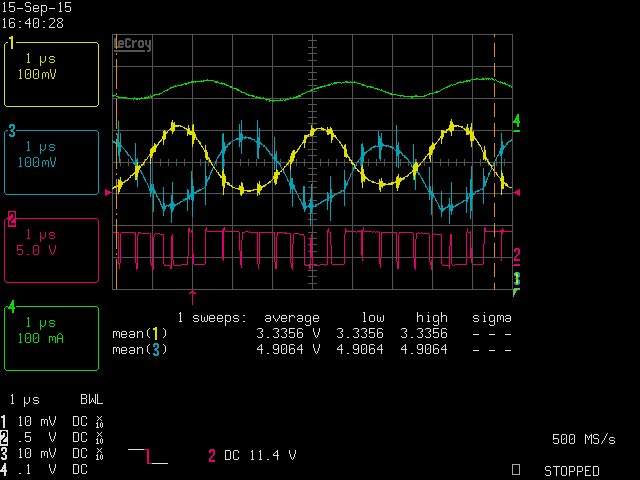
i am using the TPS62750 in a USB WLAN application. I'm experiencing stability issues, the output voltage is oscillating, i can see a strong jitter at the SW-Node of the regulator.

I can also reproduce this using the TPS62750EVM also, by changing the output capacitor (C5): Tantalum capacitor, 47µF ESR = 1,6E : not stable, Electrolytic capacitor, 100µF, 0,35E: stable.

Is it possible, to get a stable output voltage at e.g. 84µF output capacitance (as in my application) by changing feedback or feed forward capacitor?I tried changing this, but with little effect.
If not, which is the minimum output capacity for 5V->3,3V for stable operation?

Thanks in advance for any response!

  • Hi,

    First thanks for ordering the EVM to evaluate the device. Working on the same layout make things easier.

    Which changes did you made on the EVM?
    In general the TPS62750 should work with a small ceramic output capacitor only (C2 =10uF on EVM) as described in DS page 19.

    What are your load conditions?
    If i have your application conditions i can have a look at this in the lab.

    Could you also provide a scope plot with Vin, Vout, SW-Node?

    Thanks & Regards,
    Michael
  • Hi,

    thanks for the fast response.
    I only replaced c5 for the said capacitors.
    I used a 22E power resistor as Load, connected by 2x1m laboratory cable. Its also oszillating with my electronic load.
    My power supply is USB cable from my PC.
    If i use no capacitor as replacement for C5, the circuit is also unstable.
  • Sorry, i forgot about the scope plot earlier.

    Channel1 is the output voltage on J4

    Channel2 is the switch node on L1

    Channel3 is the input voltage on J1

    Channel4 is the input current

    I use a DC-offset on Channel 1 and 3, see mean values

    The spikes on Channel 1 and 3 are measurement error (no spikes, if i disconnect the switching node).

  • Hi,

    thanks for all the additional information's.

    You were right. The Device is compensated for big output capacitance.
    So we recommended a minimum Cout of 100uF for stable operation.

    Could you share more details of your power requirements?
    Maybe there are other devices which fits better to your application with smaller Cout. (eg TPS62250)

    Thanks & Regards,
    Michael
  • Thanks for the response.

    because of the project schedule, I cannot do a redesign. But I may be able to increase the capacity to 100µF.

    I use the TPS62750 in a WLAN USB solution.The board contains a WLAN-Module (unknown circuit) and additional 84µF on board. in my application, board space is limited, so i tried to avoid a separate solution for Inrush limiting (e.g. a source follower).  Normally i would prefer an LDO with softstart, but this is not possible here because of thermal reasons.

    The TPS62750 seemed to be the easiest was to achieve USB-conformity with an unknown circuit and minimum board space.

    I should have bought the EVM before designing the circuit...

  • Hi,

    Yes, please try to increase the capacity and check the stability with your design.

    We also have a bunch of switching devices with soft start function.

    Thanks & Regards,
    Michael