This thread has been locked.

If you have a related question, please click the "Ask a related question" button in the top right corner. The newly created question will be automatically linked to this question.

TPS630250 enable controlling using reset IC.

Other Parts Discussed in Thread: MCP809, TPS630250

Hello ,

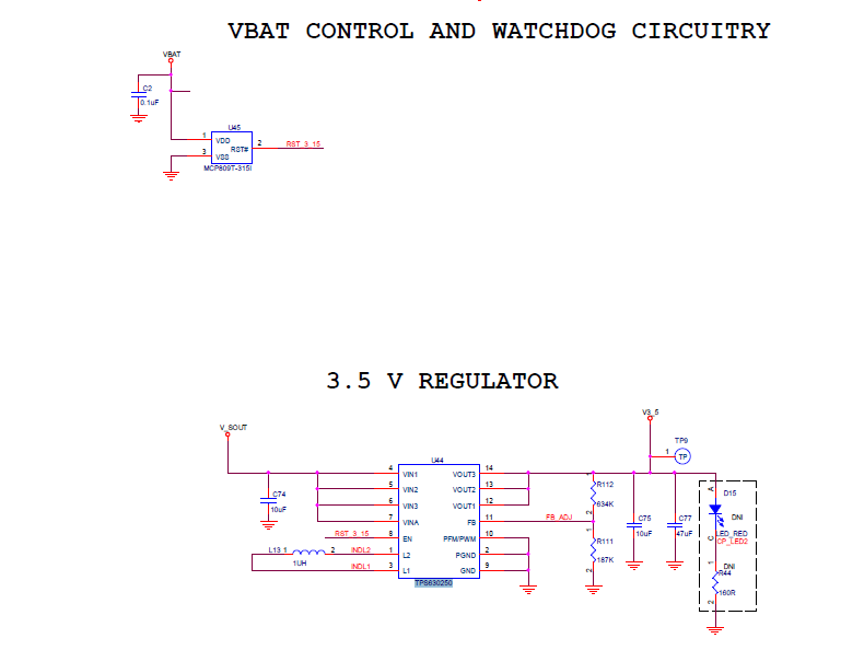
I am using TPS630250 for my design, here I am controlling the regulator by using a reset IC MCP809.

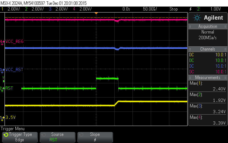
I can control the regulator when voltage drops below 1.5V successfully.

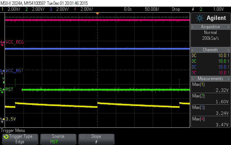
but when I am increasing the supply voltage from 3V,i am getting the stable output from regulator only from some 3.4V.

can anybody help me for solving this issue.

  • Could you verify that the reset signal is not present when increasing the voltage?
    How does the behavior appear when being not stable? Can you share some measurements with an oscilloscope?
  • Hello,

    Attached is the waveform while increasing the supply voltage .

    we are getting a stable output from regulator only when supply is at 3.4V.

  • From this waveform, it looks as the device is just enabled for a very short time every ~250ms. It seems as the device is shut down again, before it is able to fully start up.

    Could it be that your input voltage drops during device start-up? This can happen if the input source is too weak.
    How is the device input connected to VBAT?
  • Hello,

    We had tried the input source with current limited at 1A.

    We had also connected the input with VBAT, but the output is same

  • In terms of source capability, what counts is the direct input to the device. Can you measure VIN (at the device) like you have done the scope waveforms for VOUT and RST. Here you will see whether VIN drops or remains stable.
  • Hello,

    pls find the attachments

  • Can you please use the same signal name on the schematic and the oscilloscope, it is hard to understand where exactly the signals are measured
    1) What is the exact part number of the reset IC you are using? There are many options and threshold specifications on the MCP809 datasheet
    2) What is the input voltage range of the circuit? What is the threshold voltage from which you expect the converter to turn on?
    3) Is RST signal (green) measured on the enable pin of the converter?

    Can you try to connect the EN pin of the device directly to the input and verify if the converter has a stable output when the supply voltage is below 3.4V
  • Hello,

    We are using the part  MCP809T-315I for VBAT control at 3.15V.

    The input voltage is from a Li-ion battery of 3.7V max,We need to control the regulator when battery voltage is at 3.15V both when charging and discharging.

    The Pink waveform is  V_SOUT as in schematics.

    Blue is  VBAT

    Green is  RST_3_15

    Yellow is V3_5

  • Thanks for the specifications.
    Can you send me the datasheet of the MCP809T-315I, the specifications for this part are not available on the MCP809 datasheet.
    Do you measure the signal on the EN input pin of the converter? If RST_3_15 (output of the watchdog) is the signal of the EN pin of the converter then there is a problem. The EN pin should be set to high AND stay high for the DCDC converter to operate.
  • Hello,

    RST_3_15 is connected to Enable pin,So same signal of RST_3_15 is there at EN pin.

    For the functioning of regulator the EN should be set high,ok

    I just only  need to control the regulator when the input voltage goes below the trip point of MCP chip(3.15V).

  • Hello ,

    I can cut off the regulator output when voltage goes below 3.15V successfully.


    but when I am increasing the supply voltage from 3.15V,i am getting the stable output from regulator only from some 3.4V.

    0005.mcp809.pdf

  • Our DCDC converter needs to stay enabled to work, in other words  EN-pin set to high.

    From the plots, I see the EN-signal (green) turns on and shuts back down, that is the reason you are not able to get a stable output rail from the DCDC converter.

    You have to make sure the output of the mp809-315, keeps the EN-pin high (always ON) when your supply voltage increases above 3.15V.

  • hello,

    Your DCDC converter can't make a dip in the supply when turned ON.that DIP is causing the reset IC to change its status.

    I just need to know how this DIP occur ,the regulator output will become stable when VBAT level rises to 3.5V.

    As per spec the regulator should turn off and turn on at the level 3.15V.

    Is this a driving issue or something like that? I am looking for a solution!!

  • During start-up, the device draws a higher current to charge the output. Please see Figure 25/26 in the datasheet.
    This could cause a dip in the input voltage (as in your scope plots) and eventually influence the status of your supervisor.

    For our DC/DC Converter, it is required to keep the EN signal high. Otherwise the deice will immediately shut down again. This is what it seems to be the case.

    To solve your issue, you need to make sure that the EN Signal of TPS630250 doesn't go away during start-up (A lower impedance path for the input could help for example).
    The solution, however, depends on your application design!
  • Hello,

    Can you please make some more clear about the point"A lower impedance path for the input could help for example"

  • The voltage decrease when drawing current from the battery defines the impedance.
    This could cause the Supervisor to reset.
    Please use this as a potential starting point for debugging your design.

    Again - the key for our DC/DC is that the enable signal doesn't go away. Otherwise it immediately shuts down again, as in your design.