This thread has been locked.

If you have a related question, please click the "Ask a related question" button in the top right corner. The newly created question will be automatically linked to this question.

Combine two UCD74120 using one UCD9244's channel

Expert 2985 points
Other Parts Discussed in Thread: UCD9244, UCD74120, UCD9222, UCD7242, UCD7232, CSD87353Q5D

Hi TI experts,

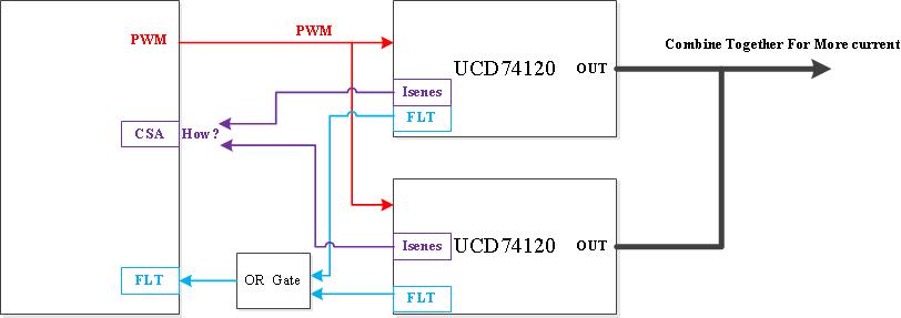
I want to acquire higher current, so I use one UCD9244's channel to generate PWM signals to control two UCD74120 simultaneously.

Two FLT signals are connected to one OR gate and then the output of this OR gate is connected to the FLT pin of this UCD9244's channel.

But how to connect two Isenes signals to one CSA pin of one UCD9244's channel?

My schematics is like this

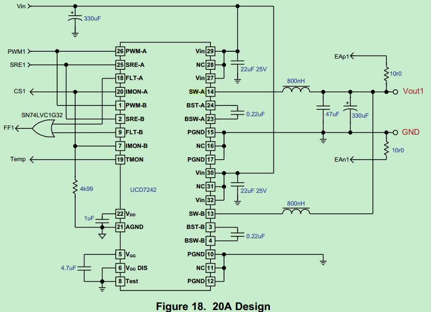
When I use the UCD9222 to connect two UCD7242s, UCD7242's Isenes is current related, so I can combine these two UCD7242's Isenes signals together.

Showing like this in the UCD9244's datasheet,

But now, the UCD74120's Isenes signals are voltage related.

1. Do I need one voltage adder? Could you show me some examples with least BOM?

2. Can I just leave the UCD74120's Isenes signals unconnected to simplify the schematics design? If the Isenes signals are unconnected that is the UCD9244 does not monitor the UCD74120's output current, can the UCD74120 work well to generate the right voltage output and reach the right output current?

Regards,

Feng

  • UCD74120 cannot be paralleled in this way, because the MOSFETs are in different chips. UCD7242's two channels can be paralleled because the MOSFETs are in the same chip so they can automatically achieve current balance.
    For high current rail you may consider discrete single phase solution UCD7232+CSD87353Q5D.

    Regards,
    Zhiyuan
  • Thanks!

    I refers this schematics K2H_K2EVM-HK_SCH_A104_Rev4_0.pdf

    In page 40, you will see one UCD9244 that is U16 controls two UCD74120s that are U10 and U44 simultaneously.

    So is this design is not good enough? Actually one TI engineer shows me that this design could be alternated.

    But for quick design, our schematics design is done already. We do not want to change the schematics dramatically.

    1. So if I retain the design showing in the figure at the top of the thread and that is what the design in the attached pdf file does, will it cause some critical damage?

    2. If no critical damage, how do I connect two UCD74120's Isenes to one UCD9244's channel?

    Maybe in the next version of our board, we will change this place!

  • The EVM operates the two UCD74120s as separate rails, but there is no current sharing mechanism between the two rails. In theory, in the worst case the two rails can conflict and cause OC shut down.

    When you tie the two UCD74120s to the same PWM, the current share is inversely proportional to the ratio of the resistances in the two phases. If the two phases are identical, the uncontrolled current share can be acceptable, given that there is enough margin (rail current <<50A). I don't have a good answer on how to connect the IMON pins. For a quick design, you need to be creative. I'm thinking, you can connect a diode anode to each IMON pin, and connect the cathode nodes together to the CS pin. The signal will be the highest current UCD74120 signal with a diode drop.

    If what you need is 26A total as is the case in EVM, and do not want to make drastic changes for a quick design, you can use a single UCD74120 which is rated at 25A.