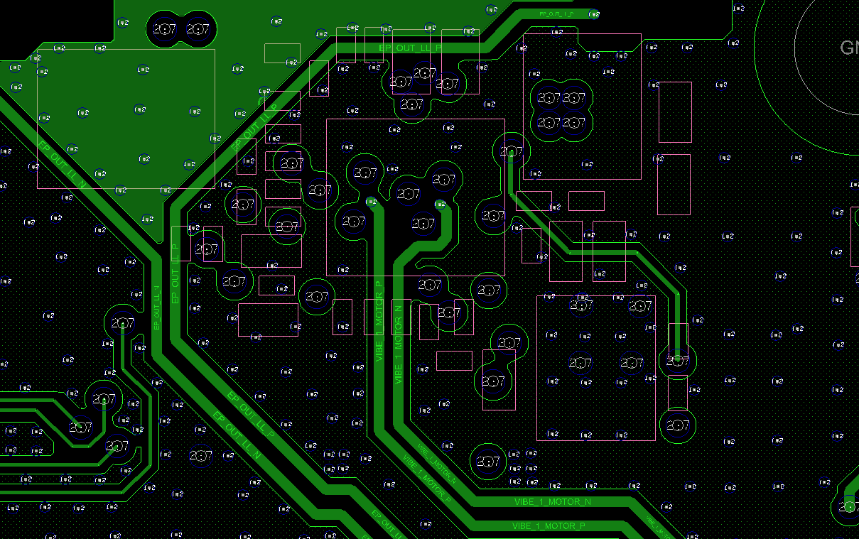
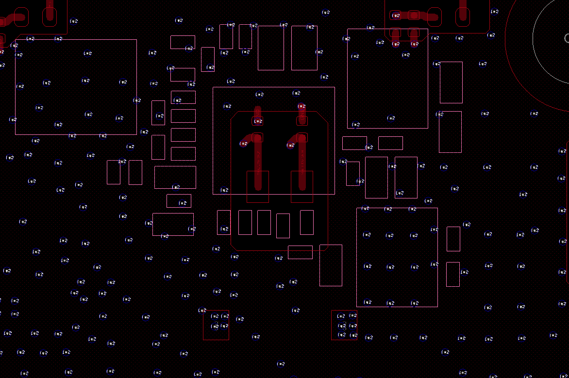
This thread has been locked.

If you have a related question, please click the "Ask a related question" button in the top right corner. The newly created question will be automatically linked to this question.

Layout review support for TPS68470

Other Parts Discussed in Thread: TPS68470

Hi TI friends:

     would you please help to review the Layout for  TPS68470 in our new project, hope below captures are enough, any question, please let me know, thanks.

Bottom layer:

Layer 7:

Layer 6:

Layer 5:

Layer 4:

Layer 3:

Layer 2:

TOP layer:

  • HI,

    I did a quick look through and see that the PGND of the boost converter and CORE buck are not directly connected to the CIN caps of the respective rails. The PGND balls must be directly connected to the CIN, preferably on the same layer as the IC.

    Please see section 11.2 layout example in the datasheet for an image representation of what I am referring to with the PGNDs.
  • Hi Michael Green:

    Thank you very much for your review.

    Due to the shield of the camera PMIC is very small. I think there is no enough room for better placement. please refer to capture below.

    And the PCB had  tapeout a few days before.

    Could you please tell me what issue will be caused with the current layout. thanks.

  • Hi,

    If the PGND for the boost and buck are not close the caps or if the loop is lengthy then high noise may be emitted either on the board or surrounding area. Watch for this during your EMI testing. Second, you may see VIN dropouts which could cause Vout over and undershoots / noise. However, if the drop out is bad enough you could cause dropouts on the Vout. You should conduct Iout transient testing at the minimum input voltage to check for the second point of concerns.
  • Hi Michael:

        Got it, thanks a lot.

  • Hi Michael Green:

         Does TPS68470 can drive IR LED which used for face recognition?

      if the answer is Yes, the TPS68470 work in Which mode when doing face recognition?

    I plan to use DRV_WLED2 to drive IR LED SFH 4715AS, due to the 1A capability of Skycam PMIC, IR LED is not expected to run at the max power.

    When doing face authentication(20-80cm), what’s the current requirement for IR LED?

    I plan to use DRV_WLED1 to drive Flash LED, What’s the normal current requirement for Flash LED when LED flashing.

    I am not experience at LED design, hope i can get your great support.

    thanks a lot.

  • Hi,

    wLEDs have a higher Vfw than the IR LED and flash wLEDs require up to ~1A as opposed to IR LEDs which need about 50mA or so. This means that there would be some mismatch. Thus, it should be tested on an EVM to know how to compensate for this. If the IR LED is not going to be on for long period of time, I suggest adding a power resistor to dissipate the excess voltage and power drop.

    Note that the mode of operation will be the same for each. Which kind of operation modes will be be planning on using for the IR and flash LEDs and will they be required to both be operated at the same time and different times. Basically, do you need them to be completely independent.