This thread has been locked.

If you have a related question, please click the "Ask a related question" button in the top right corner. The newly created question will be automatically linked to this question.

LM3444

Other Parts Discussed in Thread: LM3444

Hello Sir,

I am planning to use 7nos of (1Watt, 3.3V, 350mA, LEDs ) for making 7 Watt AC LED bulb using LM3444 (non isolated, buck mode), I have gone through the datasheet and I hope it is possible. My question is : Is there any changes or modification required for making the best use of LM3444? or The design I have considered is allright? Any tips from the experts.

Also, if successful, I am again considering for using 5 nos of (2Watt, 3.3V, 750mA, LEDs) for making 10 Watt AC LED Bulb using the same LM3444? I am starting from scrap, from Grass Root level, so any feedback or advice or suggestions will be much more helpful to me and highly appreciated. 

My main concern for using this LM3444 IC is to make the BOM footprint as small as possible to fit in the LED bulb casing. 

Also there is one IC from BPS, IC no is BP2832A, which is also another option for me, and the component count is very low as compared to LM3444. So, am in Dilemma which IC to choose. Asking for sincere and honest advice from the experts. Thank you.

  • Hello,

    Yes, it's a fairly simple part to use.  I do have a few questions:

    Does it need to be power factor corrected?  Are you planning on using the valley fill circuit or something else?  Are you planning on a custom inductor so you can power the IC from the inductor (for better efficiency)?

    Valley fill requires two electrolytic capacitors but if designed correct will have almost no light ripple.

    for your 10 watt design the efficiency will suffer a bit because the overall stack voltage is around 16-17 volts.

  • Thank you Irwin,

    Yes, PF correction is needed. What is the other options beside Valley fill circuit, reducing the BOM & footprint?

    I am confused for custom inductor, but will definitely go for small footprint, sacrificing some efficiency.

    Any other ICs from TI, for low cost and offline AC driver compatible? Please suggest.

    Thank you.

  • One more thing, which is better when compared for circuit complexity? IC Driver with In built HV MOSFET or external MOSFET (for LM3444) ?
  • Merry Christmas & Happy New Year TI team,

    Irwin, As you were mentioning the overall stack voltage for 10Watt design is 17V, I have decided to use 10 nos of 3030 SMD LEDs of 1W each, bringing the stack voltage to around 35V, I thin it is ok with LM3444. Please advice.

    Another thing, Vbuck for LM3444 is adjustable right? according to the no of LEDs in the string used. How do you set Vbuck and I(LED) current?

    My previous design requires, 23.1V, 350mA, and the new design requires 35V, 150mA. Please advice what min no of components to be replaced or changed? Thank you.

  • Hello,

    Please see AN-2083, it is close to what you want to do.  Vbuck will be whatever the string voltage is, the current will need to be adjusted to suit the LED stack voltage (changing the current sense resistor, R14).  The design is also for triac dimming, a few parts can be removed if not desired.

    This also includes EMI filtering, quick start-up using Q1 to provide IC bias.  It would be a good starting point for your design.

    As for internal or external MOSFETs.  Internal has less components but also less freedom to adjust circuit function to pass EMI.  Internal MOSFET will also cause the IC to run hotter and limit output power.

    AN-2083 does not require a custom inductor and is not valley fill.

    There are more components with this than the other part you mentioned but this is triac dimmable, power factor corrected (which I don't think you can do with the other part), quick start-up and will pass conducted EMI.

  • Thank you for the suggestions, I will go through it  AN-2083 and if there is a problem in conceiving the design, I will consult with you. 

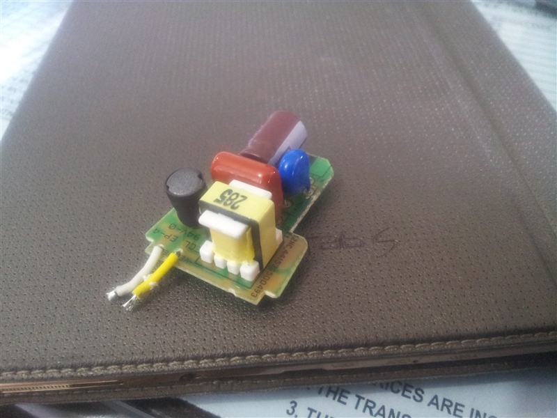
  • Can you tell me the type of component in Yellow Colour. I presume it is Inductor as It has only two pins. But looked up on net and could not found except miniature transformers with same looks. But these miniature transformers have atleast 8 pins and it has only two pins. I am confused. 

    If it is inductor, can I replace with SMD Indcutor with the calculated value from the AN 2083 note to be used in my project. 

    The above circuit is for local AC LED bulb kit. Out of curiosity I opened it up and found the yellow Inductor or Transformer. All other components I can figure it out. Can you help me sort out? Thanks.

  • If it only has two pins it is not a transformer, it is an inductor.  AN 2083 values are for a LM3444 design and most likely will not work for calculating an inductance value for something else.  Do you know if the above is a buck, buck-boost or boost?  Continuous, Discontinuous or critical conduction mode?  There is a lot to figuring out component values and operation when designing circuits that is why we provide reference designs and EVMs.

    You could pull the part from the board and measure the inductance but that doesn't mean a replacement SMT part will work.  There is core loss, core saturation (volt seconds) and DCR to consider as well as a lot of other things.

  • Hello Irwin,

    Yes, you are right. It is an inductor with only two pins. What are these inductors called? I know smd inductors, bead inductors, radial inductors, but could not find the topology or proper typical name for this inductor (searched on google). I have inquired through some of our suppliers in India. They told me that they do not know these types of inductors, and they have not seen, though they told me they have similar small miniature transformers looking same. Out of curiousity I dismantled and found that it is of around 380 turns, with 6ohm internal resistance, with metal core.

    The circuit that I have reversed engg (lolzzzz...) is a buck type with critical conduction mode, and it has internal HV 500V Mosfet. As compared with LM3444, the BOM are very less. So my doubt is, Can i work with LM3444 with the minimum features like without Valley Fill, Line EMI filter on input side, no PFC? I noted after analysing these ICs and Circuits, LM3444 is highly efficient with extra components. So, simply to run without features LM3444, is it worth it or should I go for local driver ICs?  Any tips or headsup will be highly appreciated.

    Thank you.

  • The LM3444 is very configurable.  You can reduce it to the base circuit that has no PFC, no valley fill.  You can pretty much set it up anyway you would like.  It will always have the external MOSFET unlike a part that has it internal.

    You have to know what you are designing to determine how to configure you circuit.  PFC or no PFC, etc.

    The inductor is a custom made based on what the designer wanted, just like if you were to design a transformer.  You pick a core set, design the gap, number of turns to do what you want it to.

  • Hi Irwin, 

    I was searching inductors online and found Vishay inductors will meet all my requirements.
    I have been studying Vishay inductors for the last few days. 
    I am planning to use the inductor for my LED Bulb Circuit (critical conduction mode) which requires LED current to be 150mA maximum (for smd LED 2835, 0.5W). 
    And from literatures, I have learned that Inductor Peak Current should be 2xLED Current. So, I select Inductor Peak current to be 300mA. 
    As given in the datasheet of Toff (min 4.5us to max 240us) & Ton (max 40us), I have calculated switching frequency Fsw, ranges from 3.57KHz to 22.47KHz, is it right? I used Fsw = reciprocal of (Ton + Toff).
    Inductor selection, L = (Vled * (Vin - Vled))/(Fsw * Ipk * Vin)
     
    they mentioned that Fsw is proportional to the input voltage. What does that mean? Min Fsw is set at lowest input voltage and vice versa. 
    As per my calculation, L turns out in the range of 892.5uH to 47mH, so for minimum foot print I select 892.5uH. 
    for calculation, I took the values,
    Vled = 47.6V (3.4*14nos)
    Vin = 220VAC (for India, 220VAC is the standard potential, but in datasheet Vin is given as the DC Bus Voltage after the rectifier bridge, so i was confused and took 220VAC)
    If there were any wrong assumptions I have done or overlooked any factors, please help me out.
    Thank you.
  • If you are using the LM3444 how do you intend on running it in critical conduction mode?  The LM3444 regulates current by off-time control and peak current.  It turns on the MOSFET until the current threshold is met then turns off a predetermined time by Coff.

    The Ton and Toff you mentioned are the limits of the IC.  A design will fall somewhere in those limits.

    Basically the equation V = L*(di/dt) will figure this out.  V for the off time is the LED stack voltage plus a diode drop, V for the on time is the applied voltage minus the LED stack.  dt for the off is what you set up Coff to do (this will allow you to calculate di for the off).  For dt on you have the di from the previous calculation.

    The LM3444 is meant to run in continuous mode though it can be run discontinuous.

    Input voltage is 220 VAC.  If you rectify that and have a large bulk capacitor the DC voltage will be 220 * sqrt(2), about 311 volts.  This will not be power factor corrected.

    If might be best to get hold of an EVM and see how it works.  You really need to know what you want to design, what switching frequency, PFC or not, critical conduction mode, continuous or discontinuous, large bulk capacitors (large LED ripple or not), etc.