Hi all,
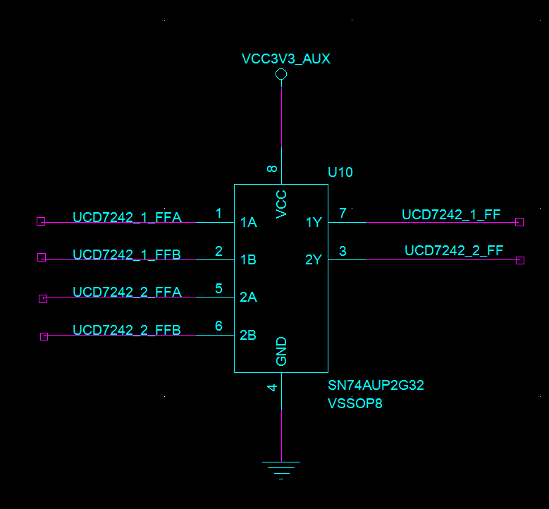
My design is as follow
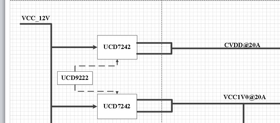
That is UCD9222's channel 1 controls the UCD7242's two channels using one identical PWM to generate CVDD that is 0.95V with 20A max current and the other UCD9222's channel controls the other UCD7242's two channels also to generate VCC1V0 that is 1.0V with 20A max output.
My schematics design is UCD9222_UCD7242.pdf
Actually, this power design is for one TMS320C6670.
Now I met a question that is VCC1V0 can be generated well but CVDD has no output and the UCD7242 that generates the CVDD reports FLT to UCD9222.
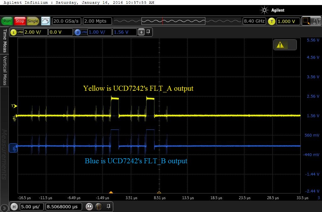
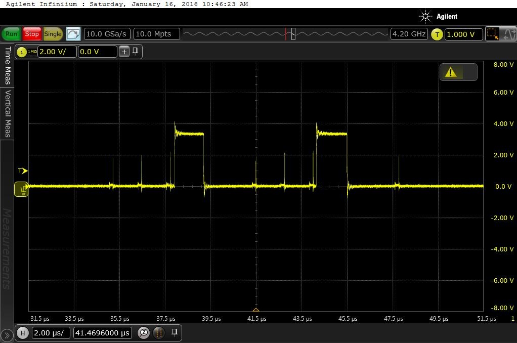
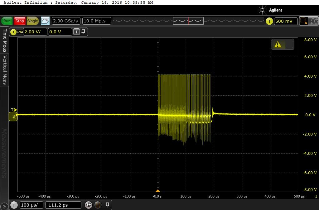
The FLT signal generated by UCD7242 is as follow. It is captured by oscilloscope.

My questions are
1. Why FLT signal is lower than 3.3V? Does this UCD7242 work in weak condition?
2. In my design the PWM signals routing to the two channels of this UCD7242 are not match. There are 320 mils skew between these two PWM signals to the respective channel of this single UCD7242. Does this skew cause the FLT?
3. The resistance between the CVDD that is the other side of the the power choke and GND is much lower than 1 Ohm with a value of 0.2 Ohm. Is it a short circuit that cause the UCD7242 ramps to a very much high current and then reports FLT?
3. One very strange phenomenon: when I powered up the other UCD7242 to generate VCC1V0 at first time, I met the FLT error same as what the UCD7242 that generates CVDD reports now. And the resistance between VCC1V0 and GND is around 0.2 Ohm also. But after I changes some fusion software configurations to the channel controls the UCD7242 that generates VCC1V0, the VCC1V0 becomes OK and the resistance between VCC1V0 and GND becomes around 10 Ohm which is a quite normal value. This phenomenon confuses me very much. Could you give me some hints to resolve this strange phenomenon?
Regards,
Feng