This thread has been locked.

If you have a related question, please click the "Ask a related question" button in the top right corner. The newly created question will be automatically linked to this question.

BQ76PL536EVM reads cell voltages incorrectly


Dear Forum, 

I recently got a BQ76PL536EVM. As the datasheet says, this has 3-6 series cell battery monitor. So we started by connecting 3 Li-ion cells in series. All the cells were roughly around the same voltage of 3.6V, totaling to 10.8V. 

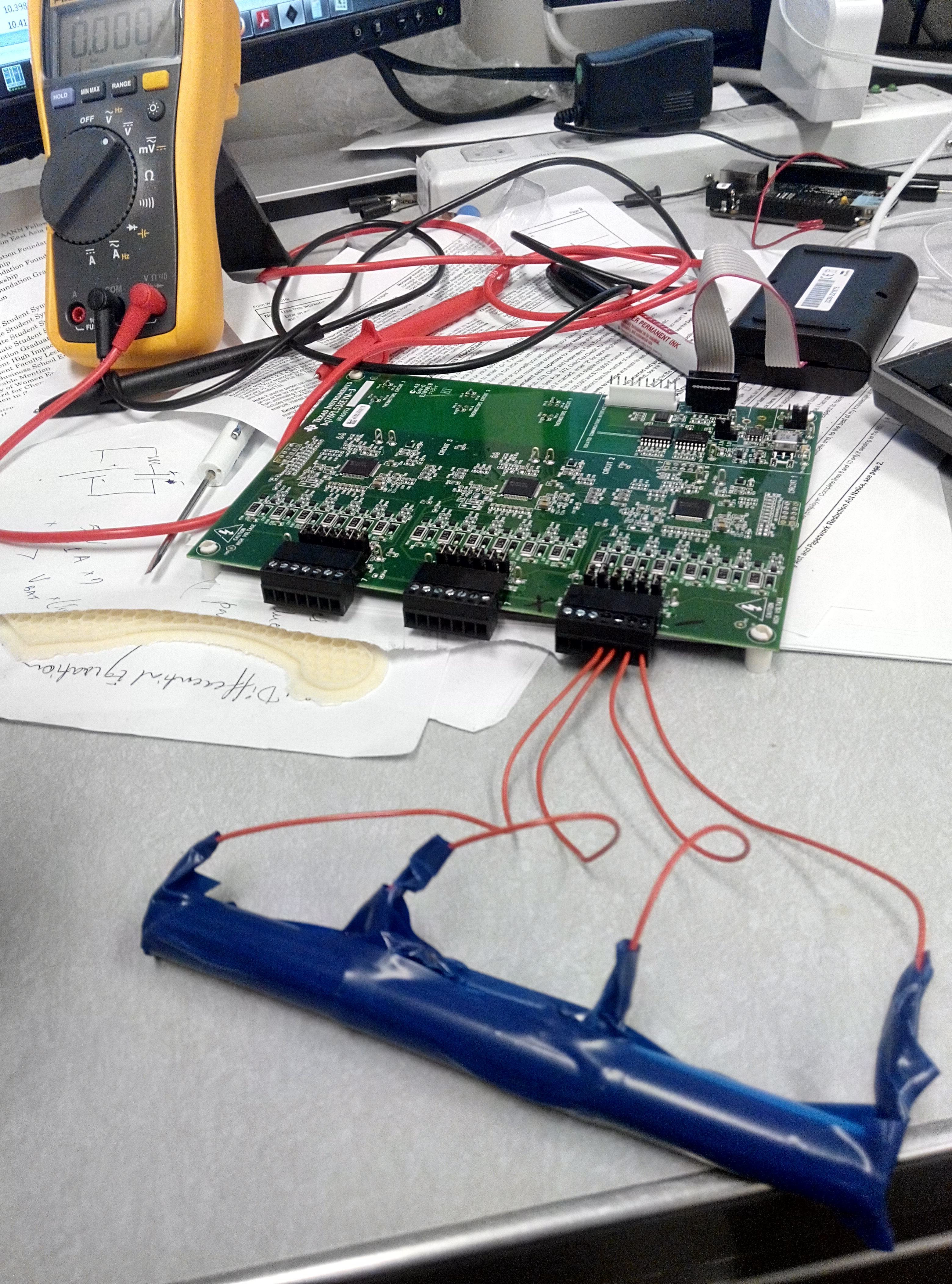
I have connected the battery pack as shown in the image, the negative of first to the right most pin and each further positive connection on the next pin. Then I connected the Aardvark adapter which was connected to a PC with the USB driver in place. When I fired up the GUI of the software, I see the following readings for cell voltages and brick voltages. 

Cell1: 3.9591

Cell2: 3.4032

Cell3: 1.4794

Brick: 10.364

I also measured the voltages with a DMM after connection, and they are I were previously, all at around 3.6V. I am also reading the same voltages across the jumpers, i.e. across the jumper of cell1 (-) and jumper across cell1 (+) and so on. Also, the voltage across TP1 and TP2, which are test points at the ends of battery pack 1 was 9.17V. Also, there is nothing connected across any of the other circuits. and the other 3 cell slots of the first circuit are also left as it is. 

Kindly help me diagnose the issue. There are multitude of inaccuracies here. The individual cell voltages are all inaccurate, actual total doesnt match shown total, and shown total doesn't match addition of shown individual cells. I have tried unchecking the "Dynamically Control the ADC"  option, but that didn't change the results much. I have restarted the GUI a few times as well. 

Thanks and regards

Chintan Pathak 

Research Scholar, University of Washington.

  • Go take a look figure 4 in the datasheet. 

    You have to connect Cell3->cell4->cell5->cell6. 

    You also have to config your setting to 3S so you can avoid UV fault. 

    Check register 0x30 and register 0x40. 

  • Dear Roger,

    Thanks for the quick response. The facts were clearly laid out in the datasheet, I should have read it more carefully.

    Shorting the header slots for cell4-cell5-cell6, improved the readings, to very good accuracy. Changed the values on 0x30 to 3S combination which is just a plain write to 0x30. Writing to 0x40 required first writing 0x35 to 0x3A (page no. 42 of datasheet), and then writing the correct bits to 0x40, and then writing back to 0x3A a value of 0x27, did remove the UV fault. A refresh cleared the red marks on the GUI. However, this resulted in an alert, which keeps on blinking, which I am assuming is totally a false positive, and might need some reset, although the Figure-16 in datasheet titled "EPROM Programming" doesnt tell anything about he method to reset the alert bit.

    Thanks again,
  • Is it Alert or Fault?
    It should be fault.

    You can find in the datahsheet how to clear Fault and Alert.
    You have to write 1 and 0 to Alert and Fault registers.

    for Gui, just click Fault[CUV] then it will clear the Fault.
    In real life, it's writing 1 and 0.

    Go to Tools-> communication monitor
    You will see actual commands send to PL536A from TI GUI.

    There is user's guide and it may help.
  • Initially before I wrote to the 0x30 and 0x40, I was seeing a CUV Fault, red block in registers and red blinking box up top. Then when I had written to 0x40, and refreshed it, the faults were cleared, and there was an alert. So this meant a green in the alert box in registers section and red blinking alert in the top section.

    I think, this alert was caused by "SLEEP" as the sleep box in register area was red. When I clicked on it, as u instructed, it cleared, alongwith the alert.

    The fact that the register boxes are clickable is not intuitive, but helpful. I noticed something else though, in place of brick voltage as the GUI was showing before, now it shows GPAI, and same value in V Stack in the top bar. I think I was careful in writing to the registers and did nothing other that what I mentioned.

    Also, what I notice is, if I try to read from 0x40, it sends me 00, I tried it several times. It was reading a value of 0x50 out of the box, which I changed to 0x53 to clear the CUV fault on batteries 4, 5 and 6. And after I wrote a 0x27 to 0x3A to copy EPROM to registers, I am always reading a 00 from 0x40. I wonder where I messed up.
  • I think the GPAI setting gets toggled due to the write to 0x40. When I restarted the GUI, the CUV faults came back on, meaning that my changes to the EPROM registers are not persistent between restarts. Thats fine, this was good learning though.
    Thanks
  • Goto Table 3 in the datasheet. 

    You will see column " RESET". 

    That's what GUI and IC will reset to. 

    You will see mostly "0" to reg 0x00 to 0x3f except reg 0x20 and 0x21. 

    Now, you will see EPROM on register 0x40 to 0x4A. 

    This is OTP and TI factory programs to all 0s. 

    yes, you can program OTP on your site if you like.

    So, in your case, you have to set reg 0x40 to 0x4A everytime you see POR.

    Does it make sense?


  • I think I have figured out the write sequence, it is 0x35 on 0x3A for unsealing the chip, and then on 0x40 with the new value, followed by 0x27 to 0x3A, and then refresh and click SLEEP and refresh to remove all alerts and faults. 

    Although when I write 53 to 0x40, which should remove the UV faults for the cells 4, 5, 6, it works as expected, but it changes the V stack output to GPAI from V Brick, which is not a major issue, just interesting to understand, whether I made an un-friendly write. What I did was added 3 (= 0b11) to the default value stored in register 0x40 which was 50 ( = 0b1010000) and wrote 53 (= 0b1010011) which should ideally just affect the last two bits and leave all the other settings unchanged. Guess something else is also happening. 

  • I think you meant 5C not 53. 

    You should go to Tool->communication monitor and you will see all the communication log between GUI and PL536A. 

    Yes, register 0x4X is GROUP 3 and we are protecting them. We don't want users to change OV, UV and OT settings accidentally.  

    Goto datasheet search for 0x40 Functional_config registers. 

    You will see GPAI_SRC bit. this bit changes between BAT and GPAI+/-. 

    As long as you have GPAI_SRC is set to 1 then you will measure BAT voltage.