We have a solar charging circuit that uses the LM5105. We have had a handful of cases where the HS and LS FETs have been damaged while testing the circuits in the factory before shipping. This is light testing (maybe 3A) consisting of connecting a battery and solar panel briefly to ensure everything looks normal. In other words we are not stressing the circuit. The failure occurs pretty rarely (maybe 1%) so it has been tricky trying to track it down. Here are the basics:
Solar Vin: 50Vdc max
Solar Power: 380W max
Vout: up to 30Vdc
Iout: 15A max
Duty cycle: microcontroller, limited to 30% to 99%
FETs, two HS, one LS are all: Fairchild FDB13AN06A0
HS gate has a 10ohm resistor and reverse diode for turn off. LS gate has a 5ohm resistor and reverse diode for turn off. I did see the other post where removing LS resistor was recommended.
Deadtime is RDT = 10k which is 100ns.
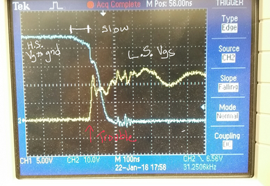
If I replace just the HS and LS FET the unit works again. I have been trying to come up with scenarios that could cause the FETs to fail but have been struggling. I did notice on one unit the HS Vgs was turning off much slower than on other units. I attempted to measure the current at the source of the LS FET, but all I had was a big wirewould resistor so I am not totally confident that I wasn’t just picking up a bunch of noise. But there did appear to be a current spike though right as the LS switched on. Next week I will put a small smd resistor on the LS source and try to get a clean reading.
Does this look like shoot through? Could shoot through like this destroy the FETs? Any ideas on why the HS would be so lazy turning off on some units? Is some sort of variation expected?
Thanks.
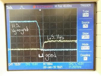
Normal unit, high to low transition.
Slow unit. HS turns off very slow.
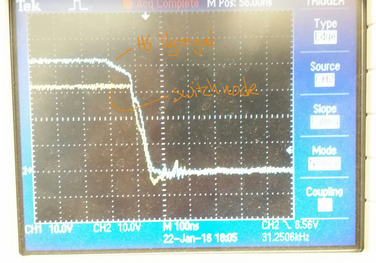
Slow unit showing Vgs. Still maybe 5V on HS when LS turns on.


