This thread has been locked.

If you have a related question, please click the "Ask a related question" button in the top right corner. The newly created question will be automatically linked to this question.

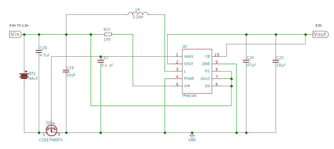
TPS61201 with about 1A with AAx3 batteries

Other Parts Discussed in Thread: TPS61201, TPS61200, TPS61030

Hello,

I am using a TPS61201 need for a handbox with about 1.2A and 3.3V when transmit and 200-300mA in normal mode. Normally the transmission takes place in milliseconds, but sometimes it can take several seconds.

You believe that this design can serve my need?

MOSFET is CSD17483F4  

C23 =  CAP CER 4.7UF 6.3V X5R 0402

C16 = CAP CER 10UF 6.3V X5R 0603

C17 = CAP CER 0.1UF 10V X5R 0402

C20 = CAP CER 47UF 6.3V X5R 1206

C22 = CAP CER 10UF 6.3V X5R 0603

R15 = RES SMD 100 OHM 1% 1/8W 0805

L5 = FIXED IND 2.2UH 1.5A 72 MOHM SMD

  • 1.2A@3.3V is too high power for the TPS61200, especially consider the 0.9V input voltage.

    could you connect the three alkaline batteries in series, and use a buck-boost converter, TPS63xxx device.
    or two battery in series, and use a boost device, TPS61030.
  • Thanks Jasper,

    Then I have to find another model of battery. With a 3.7V output and at least 3.000mAh. That somehow I can solder to the PCB, because the manufacturer of hand-held enclosure only available AA x 2, AA x 3, AAA x 4 and No Battery versions.  And I think AA or AAA batteries are just for this.

    I need to power supplied a RF module of 3V3 500mW NarrowBand (700mA TX) (35mA RX) (8uA stby). Also a Cortex M0+ and a CoG Display, about 100-150mA max. And one module GSM, 500mA max.

    All components are 3V3 (RF module, Cortex M0+, CoG Display)  except GSM module thats is to 3V8 typical, 3V3 minimal, 4V2 max.

    I need to charge via USB (micro-b).

    You can recommend to me one TI solution for this?

    Best regards,

    --javier

  • Javier
    try to understand your requirement.
    1. the system output voltages are 3.3V and 3.8V.
    2. the output current for 3.3V is 850mA
    3. The output current for 3.8V is 500mA max (average or peak current?)
    4. power supply AA x 2, AA x 3, AAA x 4 and No Battery versions? (which kind of battery? it seem to be chargeable. why not lithium-ion battery)
  • Hi,

    These are the electrical characteristics for the cellular module:

    Electrical & Sensitivity
    Output power packet mode worst case per
    radio technology (application core only)
    • 500 mA @ WCDMA 850 (B5)
    • 630 mA @ WCDMA 2100 (B1)
    • 300 mA @ EDGE class 12(4Tx)
    • 350 mA @ GPRS class 12(4Tx)
    Standby GSM / W-CDMA
    • 3mA / 1.7 mA
    Supply voltage
    • Nominal: 3.8 VDC
    • Range: 3.2 – 4.4 VDC (Each core plus RTC
    can have a separate supply)
    • Peak battery current: 2200 mA

    For the Display 3.3V:

    Notes: 1. Driver Method: 1/33 duty, 1/6 bias, VDD 3.0V, VLCD 6.0V 2. Display Type: FSTN/Positive/Transflective 3. Viewing Angle: 6:00 4. Operating Temp: -20°C ~ 70°C 5. Storage Temp: -30°C ~ 80°C 6. Driver: ST7565R 4-Line SPI 7. Backlight Type: Side Red, 3.0V/20mA 8. RoHS Compliant

    For the 500mW Narrow Band module:

    Consumption & needs

    • Power supply : 3-3.6V
    • Consumption (standby) : 8 μA
    • Consumption (RX) : 40mA
    • Consumption (TX) : 700mA (@27dBm)

    And one ARM Cortex M0+

    About battery type, I was also thinking in rechargeable Lithium battery. Some of Lithium-ion, LiPoly or LiFePO4. In prismatic format. With at least 2.200mAh.

    www.tenergy.com/.../Rechargeable-Batteries-Category

    www.greatpowerbattery.com.hk/rechargeable.html

    Thanks ands regards.

    Javier

  • Hi
    it should be more easier if using lithium-ion battery. power the GSM module directly with the battery. and a buck converter generating 3.3V for the other device. t but battery lifetime could suffer as the battery voltage should be higher than 3.3V.